

2024 Chevrolet Silverado Fuses and Fuse Box Diagram User Guide
This guide covers 2024 Chevrolet Silverado fuses and fuse box diagram. Find each fuse’s location, function, and troubleshooting suggestions to maintain your vehicle’s electrical system and performance.
2024 Chevrolet Silverado 1500 Specs, Price, Features, Mileage And Review
Video: 2024 Chevrolet Silverado Fuses
Electrical System
Electrical System Overload
The vehicle has fuses and circuit breakers to protect against an electrical system overload.
When the current electrical load is too heavy, the circuit breaker opens and closes, protecting the circuit until the current load returns to normal or the problem is fixed. This greatly reduces the chance of circuit overload and fire caused by electrical problems.
Fuses and circuit breakers protect power devices in the vehicle.
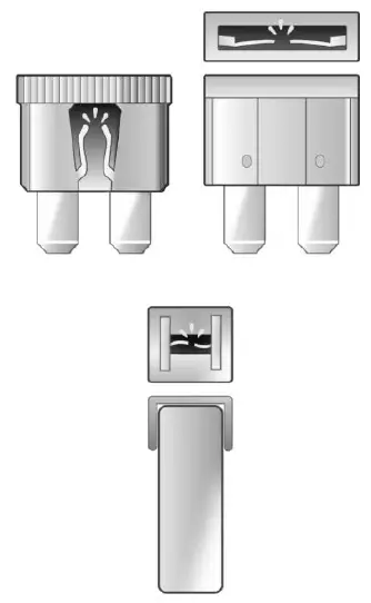
If there is a problem on the road and a fuse needs to be replaced, the same amperage fuse can be borrowed. To check a fuse, look at the band inside the fuse. If the band is broken or melted, replace the fuse. Be sure to replace a bad fuse with a fuse of identical size and rating.
Replacing a Blown Fuse
- Turn off the vehicle.
- Locate the fuse puller in the engine compartment fuse block.

- Use the fuse puller to remove the fuse from the top or side.
- If the fuse must be replaced immediately, borrow a replacement fuse with the same amperage from the fuse block. Choose a vehicle feature that is not needed to safely operate the vehicle. Repeat Steps 2-3.
- Insert the replacement fuse into the empty slot of the blown fuse.
At the next opportunity, see your dealer to replace the blown fuse.
Headlamp Wiring
An electrical overload may cause the lamps to go on and off, or in some cases to remain off. Have the headlamp wiring checked right away if the lamps go on and off or remain off?
Windshield Wipers
If the wiper motor overheats due to heavy snow or ice, the windshield wipers will stop until the motor cools and will then restart. Although the circuit is protected from electrical overload, overload due to heavy snow or ice may cause wiper linkage damage. Always clear ice and heavy snow from the windshield before using the windshield wipers. Vehicle Care 271 If the overload is caused by an electrical problem and not snow or ice, be sure to get it fixed.
Fuses and Circuit Breakers
The wiring circuits in the vehicle are protected from short circuits by a combination of fuses and circuit breakers. This greatly reduces the chance of damage caused by electrical problems.
Danger
Fuses and circuit breakers are marked with their ampere rating. Do not exceed the specified amperage rating when replacing fuses and circuit breakers. The use of an oversized fuse or circuit breaker can result in a vehicle fire. You and others could be seriously injured or killed.
Warning
Installation or use of fuses that do not meet GM’s original fuse specifications is dangerous. The fuses could fail, and result in a fire. You or others could be injured or killed, and the vehicle could be damaged.
See Accessories and Modifications 0 340 and General Information 0 340. To check or replace a blown fuse, see Electrical System Overload
Engine Compartment Fuse Block
If the vehicle has a diesel engine, see the Duramax diesel supplement. The engine compartment fuse block is in the engine compartment, on the passenger side of the vehicle.
Press the clips on the sides and lift the cover to access the fuse block.
Caution
Spilling liquid on any electrical component of the vehicle may damage it. Always keep the covers on any electrical component.
A fuse puller is available in the left instrument panel end cap. The vehicle may not be equipped with all of the fuses, relays, and features shown.
| Fuses | Usage |
| 1 | – |
| 2 | – |
| 3 | Headlamp Left |
| 4 | Headlamp Right |
| 6 | – |
| 7 | Exterior Lighting Module 4 |
| 8 | – |
| 9 | – |
| 10 | Exterior Lighting Module 6 |
| 11 | Body Control Module 3 |
| 12 | Rear Defog |
| 13 | Washer Front |
| 14 | – |
| 15 | – |
| 16 | – |
| 17 | IECL 1 – Instrument Panel Fuse Block Left 1 |
| 19 | DC/AC Inverter |
| 20 | IECR 2 – Instrument Panel Fuse Block Right 2 |
| 21 | – |
| 22 | IECL 2 |
| 24 | Fuel Heater |
| 25 | EBCM – Electronic Brake Control Module |
| 26 | – |
| 27 | Horn |
| 28 | Park Lamp Mirror/Grill |
| 29 | – |
| 30 | Exterior Lighting Module 3 |
| 31 | Exterior Lighting Module 1 |
| 32 | – |
| 33 | NOT R/C |
| 34 | Radars |
| 37 | MISC IP Headline Ignition |
| 38 | Seat Fan Ignition |
| 39 | TIM IGN – Trailer Interface Module Ignition |
| 40 | MISC Body Ignition |
| 41 | Trailer Parking Lamp |
| 42 | – |
| 44 | DEFC Ignition – Diesel Exhaust Fluid Controller Ignition |
| 45 | Secondary Axle Motor |
| 46 | Engine Control Module/ Transmission Control Module/Integrated Chassis Control Ignition |
| 47 | – |
| 48 | – |
| 49 | Transmission Auxiliary Oil Pump |
| 50 | A/C Clutch |
| 51 | Transfer Case Control Module |
| 52 | Front Wiper |
| 53 | Center High Mounted Stoplamp |
| 54 | – |
| 55 | Trailer Backup Lamp |
| 56 | SADS – Semi-Active Damping System |
| 57 | TTPM/SBZA – Side Blind Zone Alert |
| 58 | Starter Motor |
| 60 | PWR/TRN Sensors 2 |
| 61 | – |
| 62 | DEFC Battery 1/Canister Vent Solenoid |
| 63 | Trailer Brake Control Module |
| 65 | – |
| 66 | Cooling Fan Motor Left |
| 67 | – |
| 68 | DEFC Battery 2 |
| 69 | Starter Pinion |
| 71 | Cooling Fan |
| 72 | Cooling Fan Right/Lower |
| 73 | Trailer Stop/Turn Lamp Left |
| 74 | Trailer Interface Module 2 |
| 75 | Integrated Chassis Control Module |
| 76 | Electric Running Board |
| 78 | Engine Control Module |
| 79 | Cabin Coll Pump |
| 80 | Powertrain Sensor 1 |
| 81 | Trailer Stop/Turn Lamp Right |
| 82 | Trailer Interface Module 1 |
| 83 | FTZM – Fuel Tank Zone Module |
| 84 | Trailer Battery |
| 85 | – |
| 86 | Engine Control Module |
| 87 | Injector B Even |
| 88 | O2 B Sensor |
| 89 | O2 A sensor |
| 90 | Injector A Odd |
| 91 | – |
| 92 | Aeroshutter |
| Relays | Usage |
| 5 | Rear Defog |
| 18 | DC/AC Inverter |
| 23 | Fuel Heater |
| 35 | Park Lamp/Front Grille Lamp |
| 36 | Run/Crank |
| 43 | Secondary Axle Motor |
| 59 | A/C Clutch |
| 64 | Starter Motor |
| 70 | Starter Motor |
| 77 | Powertrain |
Instrument Panel Fuse Block (Left) Work Truck and Custom
If equipped with a Work Truck or Custom trim, the left instrument panel fuse block access door is on the driver-side edge of the instrument panel.
A fuse puller is available in the left instrument panel end cap. Uplevel Shown, Base Level Similar
If equipped with a Uplevel or Base Level trim, the left instrument panel fuse block access door is under the steering wheel on the driver’s side.
A fuse puller is attached to the access door. Pull off the cover to access the fuse block. The vehicle may not be equipped with all of the fuses, relays, and features shown.
| Fuses | Usage |
| F1 | Rear Heated Seats Left/ Right |
| F3 | – |
| F4 | – |
| F5 | Spare |
| F6 | Heated and Ventilated Seats Left/Right |
| F8 | – |
| F9 | EOCM – End Object Control Module/Park Assist |
| F10 | – |
| F11 | – |
| F12 | Passenger Power Seat |
| F13 | – |
| F14 | Data Link Connector |
| F15 | – |
| F16 | AMP |
| F17 | MFEG – Multifunction Endgate Control |
| F18 | – |
| F20 | Endgate |
| F22 | Rear Sliding Window |
| F23 | Driver and Passenger Memory Seat Module |
| F24 | – |
| F25 | – |
| F26 | – |
| F27 | – |
| Circuit Breakers | Usage |
| CB1 | – |
| Relays | Usage |
| K1 | Rear Sliding Window Open |
| K2 | Rear Sliding Window Close |
| K3 | MFEG – Multifunction Endgate Control High |
| K4 | – |
| K5 | MFEG – Multifunction Endgate Control Minor |
| K6 | MFEG – Multifunction Endgate Control Low |
| K7 | – |
| K8 | – |
Instrument Panel Fuse Block (Right)
The right instrument panel fuse block access door is on the passenger side edge of the instrument panel.
Pull off the cover to access the front of the fuse block.
To access the back of the fuse block:
- Push the tab at the top of the fuse block down.
- Pull the top of the fuse block outward.
- Reverse Steps 1–2 to reinstall.
 Back
Back
The vehicle may not be equipped with all of the fuses, relays, and features shown.
| Fuses | Usage |
| F1 | Right Doors |
| F2 | Left Doors |
| F3 | – |
| F4 | ELM – Exterior Lighting Module 2 |
| F5 | ELM – Exterior Lighting Module 7 |
| F6 | Front Blower |
| F8 | Left Front Window Switch |
| F10 | Steering Tilt/Upfitter Vehicle Module/Exterior Lighting Module 5 |
| F11 | Video Processing Module/ Overhead Control Camera |
| F12 | Central Gateway Module/ Telematics Control Platform/Column Lock/ Driver Monitor System |
| F14 | – |
| F17 | Steering Wheel Controls |
| F18 | – |
| F19 | – |
| F20 | – |
| F21 | – |
| F22 | Heated Steering Wheel |
| F23 | – |
| F24 | – |
| F25 | Spot Lamp Left/Right |
| F26 | USB Ports/Special Equipment option Retained Accessory Power |
| F27 | Accessory Power Outlet/ Retained Accessory Power |
| F28 | Accessory Power Outlet/ Battery |
| F30 | Sensing and Diagnostic Module/Automatic Occupant Sensing/ Integrated Center Stack/ Instrument Panel Cluster/Heads-up Display/Humidity |
| F31 | Body Control Module 2 |
| F32 | Remote Function Actuator/ Wireless Charging Module/ Aux Jack/Center Stack Module Aux Jack/Trailer Brake Control Switch |
| F33 | Body Control Module 4 |
| F34 | – |
| F40 | – |
| F41 | – |
| F42 | Electric Park Brake Switch |
| F43 | – |
| F44 | Shifter Interface Board |
| F45 | Radio Low |
| F46 | – |
| F47 | – |
| F48 | Transmission Control Module |
| F49 | Body Control Module 1 |
| F50 | – |
| F51 | Battery 1 |
| F52 | Battery 2 |
| F53 | – |
| F54 | Sunroof |
| F55 | Driver Power Seat |
| F56 | DC/DC Converter Battery 1 |
| F57 | DC/DC Converter Battery 2 |
| F58 | – |
| Circuit Breakers | Usage |
| 1 | Accessory Power Outlet 1 |
| 2 | – |
| 3 | – |
| 4 | – |
| Relays | Usage |
| K1 | – |
| K2 | Retained Accessory Power/ Accessory 1 |
| K4 | – |
| K5 | – |
FAQs
The fuse box in the 2024 Chevrolet Silverado is typically located in the engine compartment or on the driver’s side dashboard.
To access the fuse box, open the hood or driver’s side door, and look for a removable panel covering the fuse box.
A fuse puller or a pair of needle-nose pliers can be useful for removing fuses. Always have the appropriate replacement fuses on hand.
The Silverado may use blade-type fuses, and they come in various amperages.
Useful Link:
View Full PDF: 2024 Chevrolet Silverado User Manual | Auto User Guide
2024 Chevrolet Silverado 1500 Specs, Price, Features, Mileage And Review
2024 Chevrolet Silverado Instrument Cluster System | How to use