
![]()
2024 RAM 1500 Fuses and Fuse Box User Guide
This Guide covers the 2024 RAM 1500 fuses and fuse box, including their locations, functions, and replacement to keep your truck’s electrical system running smoothly.
2024 RAM 1500 Specs, Price, Features, Mileage And Review
Video: 2024 RAM 1500 Fuses
FUSES
General Information
WARNING!
- When replacing a blown fuse, always use an appropriate replacement fuse with the same amp rating as the original fuse. Never replace a fuse with another fuse of a higher amp rating. The use of a fuse with a rating other than indicated may result in a dangerous electrical system overload. If a properly rated fuse continues to blow, it indicates a problem in the circuit that must be corrected. Never replace a blown fuse with metal wires or any other material. Do not place a fuse inside a circuit breaker cavity or vice versa. Failure to use proper fuses may result in serious personal injury, fire, and/or property damage.
- Before replacing a fuse, make sure that the ignition is off and that all the other services are switched off and/or disengaged.
- If the replaced fuse blows again, contact an authorized dealer.
- If a general protection fuse for safety systems (air bag system, braking system), power unit systems (engine system, transmission system), or steering system blows, contact an authorized dealer.
CAUTION!
If it is necessary to wash the engine compartment, take care not to directly hit the fuse box and the windshield wiper motors with water.
The fuses protect electrical systems against excessive current.
When a device does not work, you must check the fuse element inside the blade fuse for a break/melt. Also, please be aware that using power outlets for extended periods with the engine off may result in vehicle battery discharge.
 Blade Fuses
- Fuse Element
- Blade Fuse with a good/functional fuse element
- Blade Fuse with a bad/not functional fuse element (blown fuse)
Underhood Power Distribution Center
The Power Distribution Center is located in the engine compartment near the battery. This center contains cartridge fuses, micro fuses, relays, and circuit breakers. A description of each fuse and component may be stamped on the inside cover, otherwise, the cavity number of each fuse is stamped on the inside cover that corresponds to the following chart.
CAUTION!
When installing the power distribution center cover, it is important to ensure the cover is properly positioned and fully latched. Failure to do so may allow water to get into the power distribution center and possibly result in an electrical system failure.
 Underhood Power Distribution Center
|
Cavity |
Cartridge Fuse | Micro Fuse | Description |
|
If Equipped |
|||
| F01 | – | 25 Amp Clear | Fuel Pump Motor / Assy Fuel Tank |
| F02 | – | – | Spare * |
| F03 | – | 5 Amp Tan | MGU * |
| F04 | – | – | Spare * |
| F05 | – | – | Spare * |
| F06 | – | 10 Amp Red | OUTPUT TO UPFITTER PDC * |
| F07 | – | – | Spare * |
| F08 | 20 Amp Blue | – | Trailer Tow Backup |
| F09 | – | 20 Amp Yellow | Trailer Stop / Turn Lamp Left |
| F10 | – | 20 Amp Yellow | Trailer Stop / Turn Lamp Right |
| F11 | – | 15 Amp Blue | ID/CLEARANCE LIGHTS * |
| F12 | 20 Amp Blue | – | Trailer Tow Park Lamp |
| F13 | – | – | Spare * |
| F14 | – | 10 Amp Red | AC Clutch |
| F15 | – | 5 Amp Tan | Intelligent Battery Sensor (IBS) |
| F16 | – | – | Spare * |
| F17 | – | 20 Amp Yellow | Air Suspension |
| F18 | – | 15 Amp Blue | AGS / Rear Axle Cooling Valve / Active Air Dam |
| F19 | – | – | Spare * |
| F20 | – | 20 Amp Yellow | Adjustable Pedals * |
| F21 | 30 Amp Pink | – | Power Side Step* |
| F22 | 50 Amp Red | – | Air Module * |
| F23 | – | – | Spare * |
| F24 | – | 20 Amp Yellow | TCM SBW |
| F25 | 40 Amp Green | – | MOD CBC 4 Exterior Lights 2 |
| F26 | 50 Amp Red | – | ESP Module |
| F27 | 30 Amp Pink | – | Front Wiper |
| F28 | – | 10 Amp Red | PCM / ECM |
| F29 | 40 Amp Green | – | ESP Module |
| F30 | – | – | Spare * |
| F31 | – | – | Spare * |
| F32 | 20 Amp Blue | – | ECM / PCM |
| F33 | 30 Amp Pink | – | Brake Vacuum Pump |
| F34 | – | – | Spare * |
| F35 | – | 10 Amp Red | PCM / ECM / Power Pack Unit (PPU) Motor Generator Unit (MGU) Wake Up * / EPS / ATMM / ESP |
| F36 | – | – | Spare * |
| F37 | – | 5 Amp Tan | R / S Output to PDC |
| F38 | – | 10 Amp Red | DTCM / Active CL TEMP VLV |
| F39 | – | 15 Amp Blue | MOD ATMM * |
| F40 | 40 Amp Green | – | Starter |
| F41 | – | 10 Amp Red | IRCAM Heaters |
| F42 | 20 Amp Blue | – | AUX SWITCH #5* |
| F43 | – | 20 Amp Yellow | MGU Coolant Pump / ADCM * |
| F44 | – | 10 Amp Red | Trailer Camera * |
| F45 | – | 10 Amp Red | ADCM * |
| F46 | 30 Amp Pink | – | Fuel Heater * |
| F47 | 30 Amp Pink | – | Rear Defroster |
| F48 | – | – | Spare * |
| F49 | 30 Amp Pink | – | Htr Ctrl * |
| F50 | 20 Amp Blue | – | AUX SWITCH #6* |
| F51 | 25 Amp White | – | FUEL PUMP MOTOR #1 * |
| F52 | – | – | Spare * |
| F53 | – | 10 Amp Red | Supply / Purging Pump * |
|
F54 |
– |
15 Amp Blue | PCM * |
| 10 Amp Red | Vapor Blocking Valve * | ||
| F55 | – | 15 Amp Blue | RT HID Headlamp |
| F56 | – | – | Spare * |
| F57 | – | 20 Amp Yellow | Horn |
| F58 | 25 Amp White | – | FUEL PUMP MOTOR #2 * |
| F59 | – | 25 Amp Clear | Injectors / IGN Coil / Glow Plug Module * |
| F60 | – | 20 Amp Yellow | ECM / PCM / ACT Short Running Valve / LTR Coolant Pump * |
| F61 | – | 15 Amp Blue | LT HID Headlamp |
|
F62 |
60 Amp Blue |
– |
Glow Plug * |
| 40 Amp Green | LTR Coolant Pump * | ||
| F63 | 20 Amp Blue | – | NOx Sensor * |
| F64 | – | 10 Amp Red | PM Sensor * |
Internal Power Distribution Center
The Power Distribution Center is located under the driver’s side instrument panel. This center contains cartridge fuses, micro fuses, relays, and circuit breakers.
2024 RAM 1500 Specs, Price, Features, Mileage And Review Fuse Cover Panel
See the following steps for accessing the interior fuses:
- Locate and remove the two screws from the lower portion of the fuse panel cover.
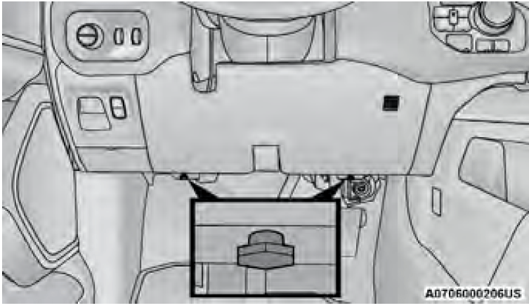 Fuse Panel Screw Locations
 - After removing the screws, gently pull both the left and right sides of the fuse panel cover to release the fastener clips.
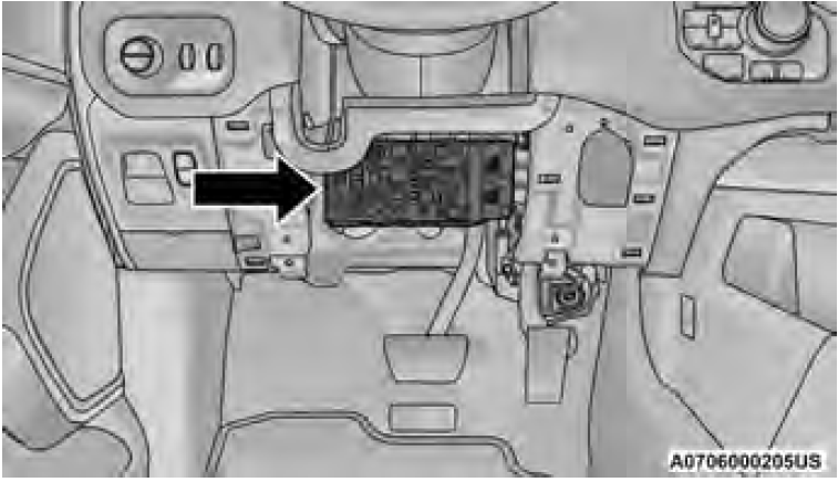 Interior Fuse Box Location
 - Reverse the procedure to reinstall the fuse panel cover.
|
Cavity |
Cartridge Fuse | Micro Fuse | Description |
|
If Equipped |
|||
| F01 | 30 Amp Pink | – | Trailer Tow Receptacle |
| F02 | – | – | Spare |
| F03 | – | 20 Amp Yellow | Module Seat Heater Front (Pass) |
| F04 | – | – | Spare |
| F05 | – | 20 Amp Yellow | Module PPU Cooling Fan * |
| F06 | – | – | Spare |
| F07 | 40 Amp Green | – | Mod CBC 3 PWR Locks |
| F08 | – | – | Spare |
| F09 | – | – | Spare |
| F10 | 40 Amp Green | – | HVAC Blower Motor |
| F11 | – | 5 Amp Tan | Output to Under-hood Power Distribution Center (UPDC) Run Coil |
| F12 | – | 25 Amp Clear | Mod Audio Amplifier / Active Noise Cancellation |
| F13 | – | 20 Amp Yellow | Mod Seat Heater Front (Driver) |
| F14 | – | 15 Amp Blue | Mod Seat Heater Front (Steering Wheel) |
| F15 A&B | – | – | Spare |
| F16 | – | – | Spare |
| F17 | – | 20 Amp Yellow | LT Spot Lamp * |
| F18 | 30 Amp Pink | – | Motor Sunshade Sunroof |
| F19 | – | – | Spare |
| F20 | – | 20 Amp Yellow | Comfort Rear Seat Module (CRSM) (Heat Rear RT) |
| F21 | – | – | Spare |
| F22 | – | – | Spare |
| F23 | – | – | Spare |
| F24 | – | 15 Amp Blue | Mod RF Hub / Mod Ignition / Mod Cluster CNN |
| F25 | 40 Amp Green | – | Mod Integrated Trailer Brake |
| F26 | – | 15 Amp Blue | Mod Cluster CCN / Mod Cyber Security / Trailer Gateway Module (360 Camera) |
| F27 | – | 5 Amp Tan | Mod Cluster CCN / Mod SGW |
| F28 | – | 10 Amp Red | Mod ORC |
| F29 | – | 20 Amp Yellow | Mod CRSM (Heat Rear LT) |
| F30 | 30 Amp Pink | – | Mod DTCM / Mod Tailgate |
| F31 | 30 Amp Pink | – | Mod CBC 1 Interior Light |
| F32 | – | 20 Amp Yellow | RT Spot Lamp * |
| F33 | – | 10 Amp Red | Assy Overhead Console / Switch 911 / Switch Assist / Sunshade / HUD |
| F34 | – | 15 Amp Blue | Frt & RR Ventilated Seat Motor |
| F35 | – | 10 Amp Red | Mod Inverter / Mtr Sunshade Sunroof / Mtr Dual Sunroof / USB Charge Only |
| F36 | 40 Amp Green | – | Mod CBC 2 Exterior Light 1 |
| F37 | – | – | Spare |
| F38 | – | – | Spare |
| F39 | – | – | Spare |
| F40 | 20 Amp Blue | – | Dome Pursuit Vehicle * |
| F41 A&B | – | 15 Amp Blue | Lumbar Support & Pass SW / Steering Column Control Module / HVAC Control Module / ICS Switch Bank / Upper Switch Bank |
|
F42 A&B |
– |
10 Amp Red |
Mod Transfer Case Switch Module (TCSM) / SBW / Electric Park Brake SW / Module TPM Trailer / Module Gateway Can-C Trailer TPM
/ Seat LT & RT Vent |
| F43 A&B | – | 10 Amp Red | Port Diagnostics / Front & Rear USB |
| F44 | – | 20 Amp Yellow | Radio / DCSD / Telematics Box Mod / Trailer Gateway Module (360) |
| F45 | 30 Amp Pink | – | Mod Door MUX Driver |
| F46 | 30 Amp Pink | – | Mod Door MUX Passenger |
| F47 | – | – | Spare |
| F48A | – | 10 Amp Red | Rear View Mirror / SW Window Passenger / Rear USB / Wireless Charging Pad Mod |
| F49 | – | 15 Amp Blue | Mod CVPM / SNSR Blind Spot / HDLP Adaptive Front Lighting Sensor (AFLS) |
| F50A | – | 10 Amp Red | Battery PACK Control Mod (BPCM) * |
| F51 A&B | – | – | Spare |
| F52 | 20 Amp Blue | – | Direct Battery Feed * |
| F53 | – | 10 Amp Red | Trailer Reverse Steering Control / Trailer Steering Control Knob |
| F54 A&B | – | 20 Amp Yellow | Power Outlet Center Seat Battery Feed Position Power Outlet Center Seat Ignition Feed Position |
| F55 | 25 Amp White | – | Upfitter * |
| F56 | 30 Amp Pink | – | Mod Network Interface * |
| F57 | 20 Amp Blue | – | Direct Battery Feed * |
| F58 | 20 Amp Blue | – | Direct Battery Feed * |
| F60 | 50 Amp Red | – | Mod Inverter * |
| F61 | – | – | Spare |
|
F62 A&B |
– |
10 Amp Red |
ITBM / Mod Occupant Class / Mod IAIR Suspension / Mod HVAC / Snsr In car Temp / Integrated Radar Camera Mod (IRCM) / Humidity Rain & Light Sensor (HRLS) / Parktronics System Mod (PTS) / Gate-way Can-C Trailer TPM Mod |
| F63 | – | – | Spare |
| F64 | – | – | Spare |
| F65 | – | 10 Amp Red | Mod ORC |
| F66 | – | 10 Amp Red | Run – Accessory Feed |
Circuit Breakers
|
Cavity |
Circuit Breaker |
Description |
| CB1 | 25 Amp | Driver Window SW Rear PWR Windows / Overhead SW Rear Defrost |
| CB2 | 25 Amp | Driver PWR Seat / Driver Seat Memory Mod |
| CB3 | 25 Amp | Passenger Power Seat / Passenger Seat Memory Mod |
Auxiliary Switches — If Equipped
Four or six auxiliary switches may be located in the lower switch bank of the instrument panel and can be used to power various electrical devices.
The functionality of the auxiliary switches can be changed via the Uconnect Settings. All switches can be configured for setting the switch type operation to the latch-ing or momentary, power source of either battery or ignition and the ability to hold the last state across key cycles. Auxiliary Switch Location
NOTE:
Holding last state conditions are met when the switch type is set to “latching” and the power source is set to “ignition” within Uconnect Settings.
The auxiliary switches manage the relays that power four or six blunt-cut wires. These wires are located under the hood to the right, near the battery.
In addition to the four or six auxiliary switch wires, a fused battery wire and ignition wire are also found in this location.
A kit of splices and heat shrink tubing is provided with the auxiliary switches to aid in the connection/installation of your electrical devices.
Fuse And Wire Color Chart
NOTE:
Fuses for the auxiliary switches can be found in the auxiliary Power Distribution Center (PDC), located in the engine compartment toward the front of the vehicle, and in front of the main PDC. Remove the upper shield to access. If equipped, additional auxiliary switch fuses will be located in the main PDC.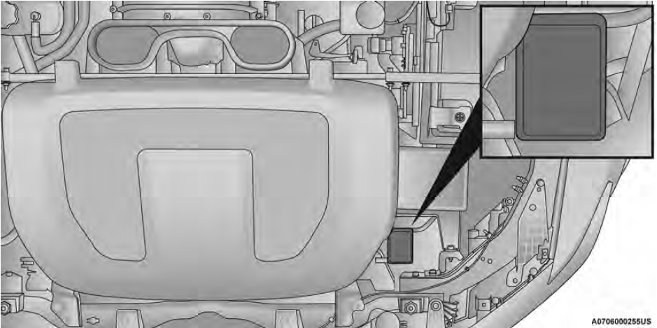 Auxiliary PDC Location
|
Circuit Function |
Fuse | Wire Color | Location |
|
If Equipped |
|||
| Aux Switch 1 | F001A – 50 Amp | Pink/Dark Blue | Auxiliary PDC |
| Aux Switch 2 | F002A – 20 Amp | Pink/Dark Green | Auxiliary PDC |
| Aux Switch 3 | F003A – 20 Amp | Pink/Violet | Auxiliary PDC |
| Aux Switch 4 | F004A – 50 Amp | Pink/Beige | Auxiliary PDC |
| Aux Switch 5* | F42 – 20 Amp | Pink/Brown | Main PDC |
| Aux Switch 6* | F50 – 20 Amp | Pink/Yellow | Main PDC |
Useful Link:
View Full PDF: 2024 RAM 1500 Owner’s Manual | Auto User Guide
2024 RAM 1500 Specs, Price, Features, Mileage And Review
2024 RAM 1500 Instrument Cluster System | How they work