
2023 Hyundai Kona-EV Fuses and Fuse Box Diagram User Guide
The 2024 Hyundai Venue Fuses and Fuse Box Diagram explains their locations, functions, and replacement. This instruction fixes electrical faults and maintains your car. 2023 Hyundai KONA Specs, Price, Features, MileageVideo: 2023 Hyundai Kona-EV Fuses
Fuses
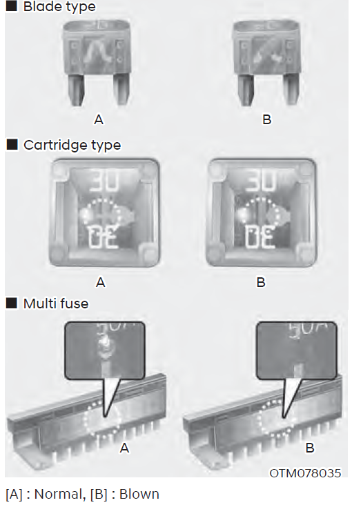 [A] : Normal, [B] : Blown
A vehicle’s electrical system is protected from electrical overload damage by fuses.
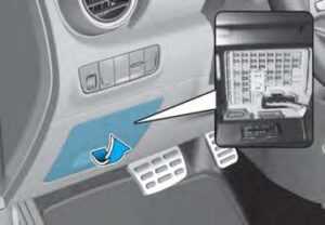
This vehicle has 2 (or 3) fuse panels, one located in the driver’s side panel bolster, the other in the motor compartment.
If any of your vehicle’s lights, accessories, or controls do not work, check the appropriate circuit fuse. If a fuse has blown, the element inside the fuse will be melted or broken.
If the electrical system does not work, first check the driver’s side fuse panel. Before replacing a blown fuse, turn the vehicle and all switches off, and then disconnect the negative battery cable. Always replace a blown fuse with one of the same rating.
If the replacement fuse blows, this indicates an electrical problem.
Avoid using the system involved and it is recommended to consult an authorized dealer.
Information
Three kinds of fuses are used: blade type for lower amperage rating, cartridge type, and multi fuse for higher amperage ratings.
WARNING
NEVER replace a fuse with anything but another fuse of the same rating.
[A] : Normal, [B] : Blown
A vehicle’s electrical system is protected from electrical overload damage by fuses.
This vehicle has 2 (or 3) fuse panels, one located in the driver’s side panel bolster, the other in the motor compartment.
If any of your vehicle’s lights, accessories, or controls do not work, check the appropriate circuit fuse. If a fuse has blown, the element inside the fuse will be melted or broken.
If the electrical system does not work, first check the driver’s side fuse panel. Before replacing a blown fuse, turn the vehicle and all switches off, and then disconnect the negative battery cable. Always replace a blown fuse with one of the same rating.
If the replacement fuse blows, this indicates an electrical problem.
Avoid using the system involved and it is recommended to consult an authorized dealer.
Information
Three kinds of fuses are used: blade type for lower amperage rating, cartridge type, and multi fuse for higher amperage ratings.
WARNING
NEVER replace a fuse with anything but another fuse of the same rating.
- A higher capacity fuse could cause damage and possibly cause a fire.
- Do not install a wire or aluminum foil instead of the proper fuse – even as a temporary repair. It may cause extensive wiring damage and possibly a fire.
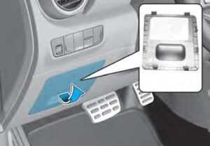
Instrument Panel Fuse Replacement
- Turn the vehicle off.
- Turn all other switches OFF.
- Open the fuse panel cover.
- Refer to the label on the inside of the fuse panel cover to locate the suspected fuse location.
- Pull the suspected fuse straight out. Use the removal tool provided in the motor compartment fuses panel.
- Check the removed fuse; replace it if it is blown. Spare fuses are provided in the instrument panel fuse panels (or in the motor compartment fuse panel).
- Push in a new fuse of the same rating, and make sure it fits tightly in the clips. If it fits loosely, consult an authorized HYUNDAI dealer.
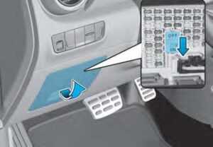 Always, place the fuse switch to the ON position.If you move the switch to the OFF position, some items such as the audio system and digital clock must be reset and the smart key may not work properly.
Information
Always, place the fuse switch to the ON position.If you move the switch to the OFF position, some items such as the audio system and digital clock must be reset and the smart key may not work properly.
Information
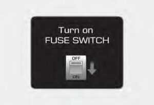 If the fuse switch is OFF, a “Turn on FUSE SWITCH” message will appear.
NOTICE
If the fuse switch is OFF, a “Turn on FUSE SWITCH” message will appear.
NOTICE
- Always place the fuse switch in the ON position while driving the vehicle.
- Do not move the transportation fuse switch repeatedly. The fuse switch may be damaged.
Motor Compartment Panel Fuse Replacement
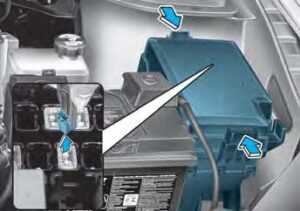

- Turn the vehicle off.
- Turn all other switches OFF. Remove the fuse panel cover by pressing the tab and pulling up.
- Check the removed fuse; replace it if it is blown.
- To remove or insert the fuse, use the fuse puller in the motor compartment fuse panel.
- Push in a new fuse of the same rating, and make sure it fits tightly in the clips. If it fits loosely, consult an authorized HYUNDAI dealer.
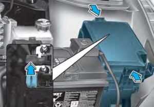
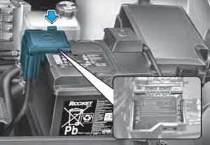
If the multi fuse is blown, it must be removed as follows:
- Turn the vehicle off.
- Disconnect the negative battery cable.
- Remove the fuse panel cover by pressing the tab and pulling it up.
- Remove the nuts shown in the picture above.
- Replace the fuse with a new one of the same rating.
- Reinstall in the reverse order of removal.
 Inside the fuse/relay box covers, you can find the fuse/relay label describing fuse/relay names and ratings.
Information
Not all fuse panel descriptions in this manual may be applicable to your vehicle. It is accurate at the time of printing. When you inspect the fuse box on your vehicle, refer to the fuse box label.
Inside the fuse/relay box covers, you can find the fuse/relay label describing fuse/relay names and ratings.
Information
Not all fuse panel descriptions in this manual may be applicable to your vehicle. It is accurate at the time of printing. When you inspect the fuse box on your vehicle, refer to the fuse box label.
 Driver’s side fuse panel
| Fuse Name | Fuse Rating | Circuit Protected |
| MODULE 5 | 7.5A | Electro Chromic Mirror, Audio, A/V & Navigation Head Unit, Front Air Ventilation Seat Module, Front Seat Warmer Module, Data Link Connector, Rear Seat Warmer Control Module, Front Console Switch |
| MODULE 3 | 7.5A | Stop Lamp Switch, BCM, IAU |
| SUNROOF | 20A | Sunroof Unit |
| LIFTGATE OPEN | 10A | Tail Gate Relay |
| P/WINDOW LH | 25A | Power Window LH Relay, Driver Safety Power Window Module |
| MULTI MEDIA | 15A | Audio, A/V & Navigation Head Unit |
| P/WINDOW RH | 25A | Power Window RH Relay, Passenger Safety Power Window Module |
| P/SEAT(DRV) | 25A | Driver Seat Manual Switch, Driver Lumbar Support Switch |
| P/SEAT(PASS) | 25A | Not Used |
| MODULE 4 | 7.5A | BCM, Crash Pad Switch, Front View Camera, Vess Unit (Speaker) |
| PDM 3 | 7.5A | Smart Key Control Module |
| SPARE | 20A | Spare |
| INTERIOR LAMP | 7.5A | Vanity Lamp LH/RH, Room Lamp, Foot Lamp LH/RH, Overhead Console Lamp, Luggage Lamp |
| MEMORY 2 | 7.5A | Vess Unit (Speaker), Electronic Refrigerant Reduced Pressure Valve, Rear Coner Radar LH/RH |
| B/ALARM HORN | 10A | Not Used |
| MEMORY 1 | 15A | A/C Control Module, Head Up Display, Instrument Cluster, BCM, Rain Sensor, Electro Chromic Mirror, Wireless Charger Unit |
| S/HEATER REAR | 20A | Rear Seat Warmer Control Module |
| AMP | 30A | AMP |
| MODULE 6 | 7.5A | Smart Key Control Module, BCM, IAU |
| MDPS | 7.5A | MDPS Unit |
| MODULE 1 | 7.5A | Active Air Flap, Hazard Switch, Data Link Connector |
Motor compartment fuse panel

Inside the fuse/relay box covers, you can find the fuse/relay label describing fuse/relay names and ratings.
Information Not all fuse panel descriptions in this manual may be applicable to your vehicle. It is accurate at the time of printing. When you inspect the fuse box on your vehicle, refer to the fuse box label.

Motor compartment fuse panel
| Type | Name | Fuse Rating | Circuit Protected |
| MULTI FUSE-3 | LDC | 150A | E/R Junction Block (Fuse – IEB 1, IEB 2, CHARGER 1, HEATED STEERING), EPCU (LDC) |
| MDPS | 80A | MDPS Unit | |
| MULTI FUSE-1 | B+ 5 | 60A | PCB Block ((Fuse – BATTERY MANAGEMENT 1, HORN, EPCU 1), IG3MAIN Relay) |
| B+ 2 | 60A | IGPM ((Fuse – S/HEATER FRT), IPS0, IPS1, IPS2) | |
| B+ 3 | 60A | IGPM (IPS3, IPS5, IPS6, IPS7) | |
| B+ 4 | 50A | IGPM (Fuse – P/WINDOW LH, P/ WINDOW RH, LIFTGATE OPEN, SUNROOF, AMP, P/SEAT (DRV), P/SEAT (PASS), S/HEATER REAR) | |
| COOLING FAN | 60A | E/R Junction Block (Cooling Fan Relay) | |
| REAR HEATED | 40A | E/R Junction Block (Rear Heated Relay) | |
| IG1 | 40A | E/R Junction Block (PDM (IG1) 2 Relay, PDM (ACC) 1 Relay) | |
| IG2 | 40A | E/R Junction Block (PDM (IG2) 3 Relay) | |
| MULTI FUSE-2 | IEB 4 | 40A | Electronic Brake Control Module |
| BLOWER | 40A | E/R Junction Block (Blower Relay) | |
| FUSE | OBC | 10A | OBC |
| CHARGER 2 | 10A | ICM Relay Box (Charge Connector Lock/ Unlock Relay), CCM Unit | |
| IG3 2 | 20A | E/R Junction Block (IG3 1 Relay, IG3 2 Relay) | |
| B+ 1 | 40A | IGPM ((Fuse – BRAKE SWITCH, MODULE 1, PDM 1, PDM 2, DOOR LOCK), LeakCurrent Autocut Device) | |
| E-SHIFTER 1 | 40A | E/R Junction Block (Fuse – E-SHIFTER 2, E-Shifter Relay) | |
| CHARGER 1 | 10A | Charge Connector Door Module | |
| IEB 1 | 40A | Electronic Brake Control Module, Multipurpose Check Connector | |
| IEB 2 | 40A | Electronic Brake Control Module |
Motor compartment fuse panel (Battery terminal cover)
Inside the fuse/relay box cover, you can find the fuse/relay label describing fuse/relay names and ratings.
Information Not all fuse panel descriptions in this manual may be applicable to your vehicle; the information is accurate at the time of printing. When you inspect the fuse panel in your vehicle, refer to the fuse panel label.
NOTICE After checking the fuse panel in the motor compartment, securely install the cover. If it is not securely latched, electrical failure may occur from water contact.
Useful Links
View Full PDF: Hyundai Kona-EV 2023 User Guide 2023 Hyundai KONA Specs, Price, Features, Mileage
2023 Hyundai Kona-EV LCD Display User Guide