
![]()
2022 Maserati Quattroporte Fuses and Fuse Box Owner’s Manual
This guide covers the 2022 Maserati Quattroporte’s fuse and fuse box layout. Understand where each fuse is located, what it controls, and how to address common electrical problems to maintain your vehicle’s reliability and performance.
2023 Maserati Quattroporte Specs, Price, Features, Mileage (Brochure)
Video: 2022 Maserati Quattroporte Fuses
If a Fuse Blows
Used Fuses Characteristics
When an electrical device is not functioning, check that the corresponding fuse is in proper working order (intact).
A Fuse intact
B Fuse blown

The vehicle mainly uses mini-and maxi fuses with blade engagement. Besides these, there are other types of fuses provided with holes for attaching to the cable connection terminals. For the replacement of these fuses contact an Authorized Maserati Dealer.
Replace the faulty fuse with a new one featuring the same rating, by using appropriate forceps added in the integrated power module and inside the cover of the rear power distribution centre.

The color identifies the value of the fuses in amperes which is also reported on them.
The table shows the match between the colour and amperage of mini and maxi fuses.
|
Type |
|
|
Mini Fuse |
Maxi Fuse |
|
Beige – 5 |
Yellow – 20 |
|
Brown – 7,5 |
Green – 30 |
|
Red – 10 |
Orange – 40 |
|
Blue – 15 |
Red – 50 |
|
Yellow – 20 |
Blue – 60 |
|
White – 25 |
|
|
Green – 30 |
|
CAUTION!
- Never replace a blown fuse with anything other than a new and suitable fuse (same rating).
- After replacing a fuse, if the fault recurs, contact an Authorized Maserati Dealer.
Position of Fuses
The fuses are located in three parts of the vehicle, namely:
- inside the integrated power module, on the right-hand side of the engine compartment;

- inside the rear power distribution center, behind the battery, on the right-hand side of the trunk compartment;

- on the fuse and relay box located in a covered area, behind the glove compartment on the dashboard’s left side.
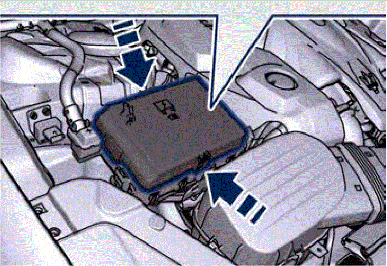
Integrated Power Module
- To access the module it is necessary to lift the hood (see “Hood Operation” in the section “Before Starting”).
- To access the fuses remove the module cover unhooking the lateral locks as shown in the picture. To recognize the reference number of the fuses in the table below, see the diagram inside the cover just removed.
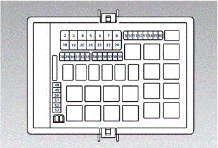
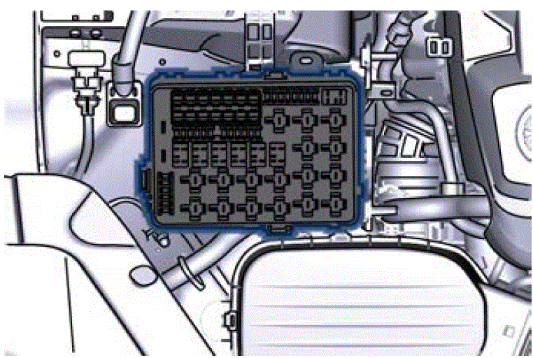
The table points out the position as featured in the cover, the type and function of the fuses included in the integrated power module.
CAUTION!
- After replacement, refit the protective cover of the module.
- If you need to wash the engine compartment, do not direct the water for too long directly on the module.
|
Ref. |
Type |
Function |
|
2 |
Maxi – 50A |
Secondary air pump relay input (3.8 V8 engine only) |
|
4 |
Maxi – 30A |
Starter motor relay in- put and starter solenoid sup-ply |
|
5 |
Maxi – 40A |
ABS-ESP pump feed |
|
6 |
Maxi – 30A |
AWD module (AWD version only) |
|
8 |
Maxi – 40A |
ABS-ESP valve feed |
|
Ref. |
Type |
Function |
|
11 |
Mini – 20A |
Horn relay input |
|
12 |
Mini – 10A |
AC compressor feed relay input |
|
14 |
Mini – 7,5A |
Alarm siren |
|
15 |
Mini – 10A |
Washer heated nozzles relay input |
|
16 |
Mini – 10A |
Enable cooling fan relay input and enable cooling oil pump relay input |
|
20 |
Maxi – 30A |
Wiper ON/OFF relay output and wiper LOW/HI |
|
28 |
Mini – 7,5A |
Drive Assist System Module (DASM) |
|
29 |
Mini – 10A |
PCM module- Starter solenoid relay coil – Voltage Body & Dash, PTC relay coil |
|
Ref. |
Type |
Function |
|
30 |
Mini – 5A |
ORC- Airbag module |
|
31 |
Mini – 5A |
ABS-ESP module |
|
32 |
Mini – 5A |
SSCU, AWD module (AWD version only), EPS and AQS |
|
33 |
Mini – 10A |
HDLP Head- lights – AFLS |
|
34 |
Mini – 15A |
Primary load to engine harness LH side |
|
35 |
Mini – 15A |
Primary load to engine harness RH side |
|
36 |
Mini – 30A |
PCM module primary load |
|
37 |
Mini – 15A |
Engine sec- ondary load |
|
38 |
Mini – 15A |
Lambda sensor |
|
39 |
Mini – 7,5A |
Flow meters, tank leakage, canister, exhaust by-pass valve relay coil and air shutter |
|
Ref. |
Type |
Function |
|
49 |
Mini – 10A |
Pedal brake switch – TCM module |
|
50 |
Mini – 15A |
+30 PCM module |
|
51 |
Mini – 30A |
Fuel pump high-speed relay input |
|
52 |
Mini – 5A |
Starter solenoid signal for PCM and voltage stabilizer |
|
53 |
Mini – 10A |
AWD module (AWD version only) |
Rear Power Distribution Center
- To access the centre it is necessary to lift the ground coverage of the trunk compartment and remove the access cover (refer to “Battery Status and Maintenance” in the section “Maintenance and Care”).
- To access the fuses, release the cover lock shown in the picture.

- Press the release latch and lift the lid from this side.
- Push the lid toward the right side to release the indicated latches on the unit. To recognize the reference number of the fuses in the table below, see the diagram inside the cover just removed.


The table points out the position as featured in the cover, and the type and function of the fuses in the rear area distribution control unit.
|
Ref. |
Type |
Function |
|
2 |
Maxi – 40A |
BCM module |
|
3 |
Maxi – 40A |
BCM module |
|
4 |
Maxi – 30A |
BCM module |
|
5 |
Maxi – 30A |
BCM module |
|
Ref. |
Type |
Function |
|
6 |
Maxi – 20A |
Sunroof module |
|
7 |
Maxi – 30A |
Driver door module |
|
8 |
Maxi – 30A |
Passenger door module |
|
9 |
Maxi – 40A |
Start&Stop: voltage sta- stabilizer, dashboard |
|
10 |
Maxi – 40A |
Start&Stop: voltage stabilizer, body |
|
11 |
Maxi – 40A |
“High Premium” stereo amplifier unit |
|
Maxi – 20A |
“Premium” stereo amplifier unit (1) |
|
|
15 |
Maxi – 40A |
HVAC front blower relay coil |
|
16 |
Maxi – 40A |
Rear window defrost relay coil (HVAC module) |
|
17 |
Maxi – 30A |
Rear LH door module |
|
Ref. |
Type |
Function |
|
18 |
Maxi – 30A |
Rear RH door module |
|
20 |
Maxi – 20A |
“Premium” stereo amplifier unit (2) |
|
21 |
Maxi – 40A |
Fuel pump (3.8 V8 engine only) |
|
22 |
Mini – 7,5A |
Rear HVAC module |
|
23 |
Mini – 10A |
Fuel door relay and RF Hub module |
|
24 |
Mini – 10A |
ITM module, ceiling light unit (front and rear), rain/lights sensor |
|
25 |
Mini – 20A |
Inverter |
|
27 |
Mini – 20A |
LH rear seat movement |
|
31 |
Mini – 25A |
LH front seat movement |
|
33 |
Mini – 20A |
RH rear seat movement |
|
Ref. |
Type |
Function |
|
34 |
Mini – 20A |
Soft Door Close latch |
|
35 |
Mini – 20A |
Rear doors sunshade |
|
36 |
Mini – 10A |
Transmission lever, Navtrak, ASBM control suspension and Hands-Free access module |
|
37 |
Mini – 25A |
Power lift- gate/trunk lid module |
|
38 |
Mini – 25A |
RH front seat movement, passenger front seat movement from rear |
|
40 |
Maxi – 20A |
Trunk power outlet |
|
43 |
Mini – 20A |
Seat passenger heater module |
|
46 |
Mini – 5A |
Rear camera |
|
47 |
Mini – 5A |
Navtrak |
|
48 |
Mini – 5A |
Surround-view |
|
Ref. |
Type |
Function |
|
49 |
Mini – 10A |
Internal temperature sensor, internal mirror and HALF |
|
51 |
Mini – 25A |
Rear seat and steering wheel heater module |
|
53 |
Mini – 25A |
Rear seat vented module |
|
54 |
Mini – 7,5A |
Blind Spot module |
|
56 |
Mini – 7,5A |
Blower front HVAC coil relay |
|
57 |
Mini – 7,5A |
Blower rear HVAC coil relay |
|
59 |
Mini – 10A |
SDC module, transmission lever, ASBM, rear tunnel stack switch |
|
60 |
Mini – 10A |
SDC module |
|
61 |
Mini – 25A |
Front console power outlet and cigar lighter |
|
62 |
Mini – 7,5A |
Front HVAC module |
|
Ref. |
Type |
Function |
|
63 |
Mini – 20A |
Blower rear HVAC |
|
64 |
Mini – 10A |
Wi-fi, rear HVAC module |
|
65 |
Mini – 10A |
Intelligent battery sensor |
|
66 |
Mini – 10A |
Wi-fi |
|
67 |
Mini – 7,5A |
USB charge outlet, sunroof |
|
68 |
Mini – 20A |
Rear sunshade module |
|
69 |
Mini – 25A |
Rear console power outlet and cigar lighter |
|
70 |
Mini – 10A |
Front HVAC module, Parking Aid Module (PAM), ASCM |
Fuse Box under the Dashboard
This box is located in an internal area that can be accessed only by removing the glove compartment on the dashboard’s left side. Considering the complexity of this operation, we recommend having the fuses replaced by an Authorized Maserati Dealer.
The table points out the position as featured in the figure, the type and function of the fuses in the box under the dashboard.


|
Ref. |
Type |
Function |
|
1 |
Mini – 7,5A |
Cluster module, CSS, SGW and DSRC (Japan version only) |
|
Ref. |
Type |
Function |
|
2 |
Mini – 15A |
Cluster module, clock |
|
3 |
Mini – 10A |
DSRC and DTV system (Japan version only) |
|
4 |
Mini – 5A |
E-call |
|
5 |
Mini – 7,5A |
Security Gateway |
|
6 |
Mini – 25A |
Radio |
|
7 |
Mini – 10A |
Column software module, CSS, USB auxiliary port |
|
8 |
Mini – 10A |
Start & Stop switch, diag- nostic outlet |
How to replace Fuse in the Maserati Quattroporte Fuse 2022
- Locate the Fuse Box:
- The fuse box in most vehicles, including the Maserati Quattroporte, is typically located either under the dashboard on the driver’s side or in the engine compartment.
- Identify the Fuse:
- Once you locate the fuse box, open it. Inside, you’ll see several fuses of different sizes and colours.
- Remove the Fuse:
- Using a pair of fuse pullers or needle-nose pliers, carefully grip the fuse you want to replace and pull it straight out of its socket. Be gentle to avoid damaging the fuse or the fuse box.
- Inspect the Fuse:
- Before inserting a new fuse, it’s a good idea to inspect the old fuse to see if it’s blown. A blown fuse will have a broken filament or appear discoloured. If the fuse is intact, the issue may lie elsewhere in the electrical system.
- Insert the Replacement Fuse:
- Take a new fuse with the same amperage rating and carefully push it into the empty socket in the fuse box. Make sure it’s seated securely.
- Test the Circuit:
- After replacing the fuse, test the component to ensure that it’s functioning properly. If the fuse blows again immediately or soon after replacement, there may be an underlying electrical issue that needs to be addressed.
- Close the Fuse Box:
- Once you’ve replaced the fuse and tested the circuit, close the fuse box securely.
- Dispose of the Old Fuse:
- If the old fuse is blown, dispose of it properly. Do not reuse a blown fuse.
Useful Links
View Full PDF: Maserati Quattroporte 2022 User Manual|Auto User Guide
2023 Maserati Quattroporte Specs, Price, Features, Mileage (Brochure)
2022 Maserati Quattroporte Indicator and Warning Lights Guide