
![]()
2024 Maserati Quattroporte Fuses and Fuse Box User Guide
The 2024 Maserati Quattroporte Fuses and Fuse Box arrangement is covered in this guide. Understanding fuse locations, amperage ratings, and replacement processes prevents electrical failures and optimizes system performance.
2024 Maserati Levante Specs, Price, Features, Mileage and Review
Video: 2024 Maserati Quattroporte Fuses
If a Fuse Blows
Used Fuses Characteristics
When an electrical device is not functioning, check that the corresponding fuse is in proper working order (intact).

- A Fuse intact
- B Fuse blown
On the vehicle are mainly used with mini-and maxi-fuses with blade engagement. Besides these there are other types of the fuse provided with holes for fixing to the cable connection terminals. For the replacement of these fuses contact the Service Network. Replace the faulty fuse with a new one featuring the same rating, by using appropriate forceps added in the integrated power module and inside the cover of the rear power distribution center.

The colour identifies the value of the fuses in amperes which is also reported on them.
The table shows the match between colour and amperage of mini and maxi fuses.
| Type | |
| Mini Fuse | Maxi Fuse |
| Beige – 5 | Yellow – 20 |
| Brown – 7,5 | Green – 30 |
| Red – 10 | Orange – 40 |
| Blue – 15 | Red – 50 |
| Yellow – 20 | Blue – 60 |
| White – 25 | |
| Green – 30 | |
CAUTION!
- Never replace a blown fuse with anything other than a new and suitable fuse (same rating).
- After replacing a fuse, if the fault recurs, contact the Service Network.
Position of Fuses
The fuses are located in three parts of the vehicle, namely:
- inside the integrated power module, on the right hand side of the engine compartment;

- inside the rear power distribution center, behind the battery, on the right hand side of the boot compartment;

- on the fuse and relay box located in a covered area, behind the glove compartment on the dashboard left side.
Integrated Power Module
- To access the module it is necessary to lift the hood (see “Open and Close the Hood” in section “Before Starting”).
- To access the fuses remove the module cover unhooking the lateral locks as shown in the picture. To recognize the reference number of the fuses in the table below, see the diagram inside the cover just removed.

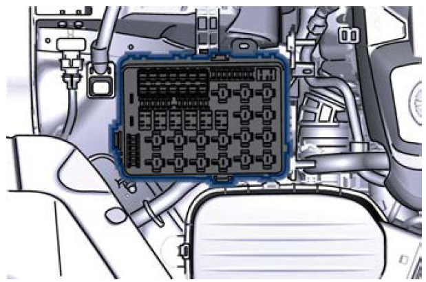
The table points out the position as featured in the cover, the type and function of the fuses included in the integrated power module.
CAUTION!
- After replacement, refit the protective cover of the module.
- If you need to wash the engine compartment, do not direct the water for too long directly on the module.
| Ref. | Type | Function |
|
2 |
Maxi – 50A |
Secondary air pump relay input (3.8 V8 – Engine only) |
|
4 |
Maxi – 30A |
Starter motor relay input and starter solenoid supply |
| 5 | Maxi – 40A | ABS-ESP pump feed |
|
6 |
Maxi – 30A | AWD module (AWD version only) |
| 8 | Maxi – 40A | ABS-ESP valve feed |
| 11 | Mini – 20A | Horn relay input |
| 12 | Mini – 10A | AC compressor feed relay input |
| 14 | Mini – 7,5A | Alarm siren |
|
15 |
Mini – 10A | Washer heated nozzles relay input |
|
16 |
Maxi – 10A |
Enable cool- ing fan relay input and en- able cooling oil pump relay in- put |
|
20 |
Maxi – 30A |
Wiper ON/OFF relay output and wiper LOW/HI |
|
28 |
Mini – 7,5A | Drive Assist System Module (DASM) |
|
29 |
Mini – 10A |
PCM module – Starter solenoid relay coil – Voltage Body & Dash, PTC relay coil |
| 30 | Mini – 5A | ORC- Air bag module |
| 31 | Mini – 5A |
ABS-ESP mod- ule |
|
32 |
Mini – 5A |
SSCU, AWD module (AWD version only), EPS and AQS |
| 33 | Mini – 10A | HDLP Head- lights – AFLS |
|
34 |
Mini – 15A | Primary load to engine harness LH side |
|
35 |
Mini – 15A | Primary load to engine harness RH side |
| 36 | Mini – 30A | PCM module primary load |
| 37 | Mini – 15A | Engine second- ary load |
| 38 | Mini – 15A | Lambda sensor |
|
39 |
Mini – 7,5A |
Flow meters, tank lackage, canister, ex- haust by-pass valve relay coil and air shutter |
|
49 |
Mini – 10A | Pedal brake switch – TCM module |
| 50 | Mini – 15A | +30 PCM mod- ule |
|
51 |
Mini – 30A | Fuel pump high speed relay input |
|
52 |
Mini – 5A |
Starter solenoid signal for PCM and voltage stabilizer |
|
53 |
Mini – 10A | AWD module (AWD version only) |
Rear Power Distribution Center
- To access the center it is necessary to lift the ground coverage of the boot compartment and remove the access cover (refer “Battery Status and Maintenance” in section “Maintenance and Care”).
- To access the fuses release the cover latch shown in picture.

- Press the release latch and lift the lid from this side.
- Push the lid toward the right side to release the indicated latches on the unit. To recognize the reference number of the fuses in the table below, see the diagram inside the cover just removed.

The table points out the position as featured in the cover, the type and function of the fuses on the rear area distribution control unit.
| Ref. | Type | Function |
| 2 | Maxi – 40A | BCM module |
| 3 | Maxi – 40A | BCM module |
| 4 | Maxi – 30A | BCM module |
| 5 | Maxi – 30A | BCM module |
| 6 | Maxi – 20A | Sunroof module |
| 7 | Maxi – 30A | Driver door module |
| 8 | Maxi – 30A | Passenger door module |
|
9 |
Maxi – 40A | Start&Stop: voltage stabi- lizer, dashboard |
|
10 |
Maxi – 40A | Start&Stop: voltage stabi- lizer, body |
|
11 |
Maxi – 40A | “High Premium” stereo amplifier unit |
| Maxi – 20A | “Premium” ste- reo amplifier unit (1) | |
|
15 |
Maxi – 40A | HVAC front blower relay coil |
|
16 |
Maxi – 40A |
Rear window defrost re- lay coil (HVAC module) |
| 17 | Maxi – 30A | Rear LH door module |
| 18 | Maxi – 30A | Rear RH door module |
|
20 |
Maxi – 20A | “Premium” ste- reo amplifier unit (2) |
|
21 |
Maxi – 40A | Fuel Pump (3.8 V8 – Engine only) |
| 22 | Mini – 7,5A | Rear HVAC module |
|
23 |
Mini – 10A | Fuel door relay and RF Hub module |
|
24 |
Mini – 10A |
ITM module, ceiling light unit (front and rear), rain/lights sensor |
| 25 | Mini – 20A | Inverter |
| 27 | Mini – 20A | LH rear seat movement |
| 31 | Mini – 25A | LH front seat movement |
| 33 | Mini – 20A | RH rear seat movement |
| 34 | Mini – 20A | Soft Door Close latch |
| 35 | Mini – 20A | Rear doors sun- shade |
|
36 |
Mini – 10A |
Transmission lever, Navtrak, ASBM control suspension and Hands Free access module |
|
37 |
Mini – 25A | Power lift- gate/boot lid module |
|
38 |
Mini – 25A |
RH front seat movement, passenger front seat movement from rear |
| 40 | Maxi – 20A | Boot power outlet |
| 43 | Mini – 20A | Seat passenger heater module |
| 46 | Mini – 5A | Rear camera |
| 47 | Mini – 5A | Navtrak |
| 48 | Mini – 5A | Surround view |
|
49 |
Mini – 10A |
Internal temperature sensor, internal mirror and HALF |
|
51 |
Mini – 25A | Rear seat and steering wheel heater module |
| 53 | Mini – 25A | Rear seat ven- ted module |
| 54 | Mini – 7,5A | Blind Spot module |
| 56 | Mini – 7,5A | Blower front HVAC coil relay |
| 57 | Mini – 7,5A | Blower rear HVAC coil relay |
|
59 |
Mini – 10A |
SDC module, transmission lever, ASBM, rear tunnel stack switch |
| 60 | Mini – 10A | SDC module |
|
61 |
Mini – 25A |
Front console power out- let and cigar lighter |
| 62 | Mini – 7,5A | Front HVAC module |
| 63 | Mini – 20A | Blower rear HVAC |
| 64 | Mini – 10A | Wi-fi, rear HVAC module |
| 65 | Mini – 10A | Intelligent bat- tery sensor |
| 66 | Mini – 10A | Wi-fi |
| 67 | Mini – 7,5A | USB charge outlet, sunroof |
| 68 | Mini – 20A | Rear sunshade module |
|
69 |
Mini – 25A |
Rear console power out- let and cigar lighter |
|
70 |
Mini – 10A |
Front HVAC module, Parking Aid Module (PAM) |
Fuse Box under the Dashboard
This box is located in an internal area that can be accessed only by removing the glove compartment on the dashboard left side. Considering the complexity of this operation, we recommend having the fuses replaced by the Service Network. The table points out the position as featured in the figure, the type and function of the fuses in the box under the dashboard.

| Ref. | Type | Function |
| 1 | Mini – 15A | Cluster module, clock |
| 2 | Mini – 5A | E-call |
| 3 | Mini – 7,5A | Security Gate- way |
| 4 | Mini – 25A | Radio |
|
5 |
Mini – 10A |
Column soft- ware module, CSS, USB auxil- iary port |
|
6 |
Mini – 10A | Start & Stop switch, diag- nostic outlet |
Useful Links:
2024 Maserati Levante Specs, Price, Features, Mileage and Review
2024 Maserati Quattroporte Instrument Cluster User Guide