
2024 Maserati GranTurismo Fuses and Fuse Box Diagram User Guide
Understand the 2024 Maserati GranTurismo fuse box layout, locations, and amperage. To maintain electrical components and prevent damage, this guide helps to find, identify, and repair blown fuses. Get step-by-step instructions for safe vehicle maintenance and reliable performance.
2023 Maserati Granturismo Specs, Price, Features, Mileage (Brochure)
Video: 2024 Maserati GranTurismo Fuses
Fuses and Fuse Box
Used Fuses Characteristics
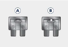
When an electrical device is not functioning, check that the corresponding fuse is in proper working order (intact).
- A Fuse intact
- B Fuse blown
On the vehicle are mainly used with mini-and maxi-fuses with blade engagement. Besides these there are other types of the fuse provided with holes for fixing to the cable connection terminals. For the replacement of these fuses contact the Service Network. Replace the faulty fuse with a new one featuring the same rating, by using appropriate forceps.
In an Emergency
The color identifies the value of the fuses in amperes which is also reported on them. The table shows the match between color and amperage of mini and maxi fuses.
| Type | |
| Mini Fuse | Maxi Fuse |
| Beige – 5 | Yellow – 20 |
| Brown – 7,5 | Green – 30 |
| Red – 10 | Orange – 40 |
| Blue – 15 | Red – 50 |
| Yellow – 20 | Blue – 60 |
| White – 25 | |
| Green – 30 | |
CAUTION!
- Never replace a blown fuse with anything other than a new and suitable fuse (same rating).
After replacing a fuse, if the fault recurs, contact the Service Network.
Position of Fuses
The fuses are located in five parts of the vehicle, namely:
- Position of Fuses
- The fuses are located in five parts of the vehicle, namely:
- inside the remote positive post, on right hand side of the engine compartment;
- inside the fuse and relay box located in a covered area, on the rear left hand side of the engine compartment;
- in the fuse and relay box located in a covered area, inside the inner central side of the boot compartment.
- on the positive post of the battery, inside the inner central side of the boot compartment.
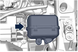
Fuses Box on the Front Left Hand Side of the Engine Compartment
- To access the module it is necessary to lift the hood (see “Open and Close the Hood” in section “Before Driving”).
To access the fuses remove the module cover unhooking the frontal locks as shown in the picture. To recognize the reference number of the fuses in the table below, see the diagram inside the cover just removed.
 The table points out the position as featured in the cover, the type and function of the fuses included in the box.
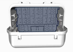
CAUTION!
- After replacement, refit the protective cover of the module.
If you need to wash the engine compartment, do not direct the water for too long directly on the module.
| Ref. | Type | Function |
| F1 | Mini – 25A | ECM input |
| F2 | Mini – 5A | Eldor Battery input |
| F3 | Mini – 25A | Primary Loads ECM LT input |
| F4 | Mini – 15A | Secondary Loads LT input |
| F5 | Mini – 20A | Secondary Loads RT input |
| F6 | Mini – 20A | Primary Loads ECM RT input |
| F7 | Mini – 7,5A | Dome console input |
| F8 | Mini – 7,5A | RFHUB input |
| R3 | Micro – 30A | HVAC Blower relay |
| R4 | Micro – 30A | Heater ADAS relay |
| R1 | Micro – 30A | Horn relay |
| R2 | Micro – 30A | Start&Stop relay |
| R3 | Micro – 30A | Starter relay |
| R6 | Micro – 30A | Cigarette Lighter relay |
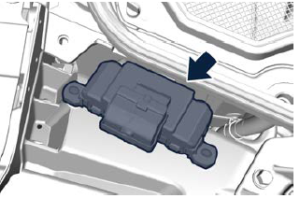
Fuses Box on the Rear Left Hand Side of the Engine Compartment
The module is located under a cover in the rear left hand side of the engine compartment. Considering the complexity of this operation, we recommend you to contact the Service Network.
 The table points out the position as featured in the cover, the type and function of the fuses included in the box.
| Ref. | Type | Function |
| F01 | Maxi – 60A | EPS1 module |
| F02 | Maxi – 60A | IBS module |
| F03 | Maxi – 15A | Cigarette Lighter / Power Outlet input |
| F04 | Maxi – 40A | IBS valves module |
| F05 | Maxi – 60A | EPS2 module |
| F06 | Maxi – 30A | ETM R1 module |
| F07 | Maxi – 50A | Engine main relay |
| F08 | Maxi – 40A | HVAC Blower input |
| F09 | Mini – 20A | BCM module |
| F10 | Mini – 10A | Horn input |
| F11 | Mini – 10A | EPS1 module |
| F14 | Mini – 15A | TCM module |
| F15 | Maxi – 20A | Starter input |
| F16 | Mini – 3A | Clockspring input |
| F17 | Mini – 10A | EPS2 module |
| F18 | Mini – 10A | BCM 3module |
| F19 | Mini – 15A | Devio, HUD & IPC module |
| F20 | Mini – 20A | LT Headlamp input |
| F21 | Mini – 20A | RT Headlamp input |
| F22 | Mini – 20A | Master F90, FXX |
| F23 | Mini – 20A | Master F7, F8 |
| F24 | Mini – 7,5A | SGW, HRLS module |
| F30 | Mini – 20A | BCM 4 module |
| F81 | Maxi – 25A | DTCM AWD module |
| F82 | Maxi – 20A | Wiper input |
| F83 | Maxi – 20A | Master F87 |
| F84 | Mini – 7,5A | ECM Module |
| F87 | Mini – 5A | ADAS input |
| F88 | Mini – 10A | A/C Com- pressor module |
| F90 | Mini – 10A | ECM/DTCM module |
| FXX | Mini – 7,5A | AQS module |
| T07 | Maxi – 50A | Engine main relay |
| T09 | Micro – 30A | BCM module relay |
| T17 | Micro – 30A | A/C Com- pressor relay |
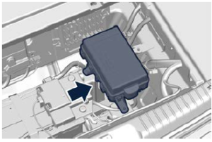
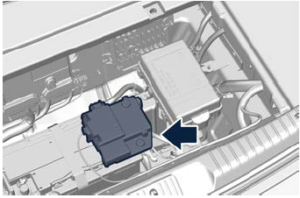
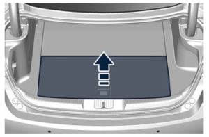
Fuse Box in the Trunk Compartment
This box is located in a covered area inside the boot compartment in the inner central side. access the fuses, ,lift the boot ground coverage, by acting on the handle, then remove the battery cover. Remove the module cover unhooking the lateral locks as shown in the picture. To recognize the reference number of the fuses in the table below, see the diagram inside the cover just removed.

| Ref. | Type | Function |
| F2 | Mini – 25A | Motor H001 input |
| F3 | Mini – 7,5A | E-Latch Passenger side in- put |
| F4 | Mini – 7,5A | E-Latch Driver side input |
| F8 | Mini – 25A | Motor H002 input |
| R1 | Maxi – 50A | VDCM Air Spring relay |
| T02 | Micro – 30A | ECU VDCM Relay |
| T05 | Micro – 30A | Fuel Pump 2 relay |
| T06 | Micro – 30A | Steering Wheel Heater relay |
| T10 | Micro – 30A | Fuel Pump 1 Relay |
| T20 | Micro – 30A | H001 Heated relay |
| T31 | Micro – 30A | H002 Heated relay |
| F01 | Maxi – 50A | Master FXX / 4+2 MTA (F3 – F4) input |
| F02 | Maxi – 30A | BCM1 module |
| F03 | Maxi – 30A | eLSD module |
| F04 | Maxi – 25A | Passenger Door module |
| F05 | Maxi – 25A | Driver Door module |
| F06 | Maxi – 25A | BCM2 module |
| F07 | Maxi – 30A | Fuel pump 2 module |
| F08 | Maxi – 30A | HI-FI module |
| F09 | Mini – 20A | ECU VDCM module |
| F10 | Mini – 10A | ORC module |
| F11 | Mini – 5A | Wireless Charger input |
| F14 | Mini – 7,5A | ITM module |
| F15 | Maxi – 40A | Air Spring mod- ule |
| F16 | Mini – 10A | IBS module |
| F17 | Mini – 7,5A | USB Charger input |
| F18 | Mini – 15A | CVPAM / H001 / H002 / ALM I025 HUB / HFRM / C070 module |
| F19 | Mini – 10A | Steering Wheel Heater input |
| F20 | Mini – 25A | Master E-Latch module |
| F22 | Mini – 20A | 12 V Boot Compartment Power Outlet |
| F23 | Mini – 25A | H001 Heated & Comfort input |
| F24 | Mini – 15A | Rear input |
| F30 | Mini – 30A | PLGM module |
| F81 | Maxi – 50A | Defrost module |
| F82 | Maxi – 30A | HI-FI 2 module |
| F83 | Maxi – 30A | Fuel Pump 1 module |
| F84 | Mini – 10A | VDCM module |
| F87 | Mini – 15A | CADM module |
| F88 | Mini – 7,5A | ORC module |
| F89 | Maxi – 30 | Rear F87 + F24 module |
| F90 | Mini – 7,5A | Heated Mir- rors & Heated Nozzles module |
| FXX | Mini – 25A | H002 Heated & Comfort input |
| T09 | Micro – 30A | Power Outlet relay |
| T17 | Micro – 30A | Defrost relay |
| R1 | Maxi – 50A | Rear Defrost Relay |
Useful Links
View Full User Guide: Maserati GranTurismo 2024 User Manual | Auto User Guide
2024 Maserati GranTurismo Instrument Cluster User Guide
2023 Maserati Granturismo Specs, Price, Features, Mileage (Brochure)