
Tata Harrier BSVI Fuses and Fuse Box User Guide
This Guide covers Tata Harrier BSVI fuses, fuse box layout, functions, placements, and blown fuse detection. Details on Tata Harrier BSVI electrical maintenance and troubleshooting is crucial.
Video: Tata Harrier BSVI Fuses
Tata Fuses Guide
Your vehicle has fuse boxes at two locations. The vehicles electrical circuits have fuses to protect the wiring from short cir-cuits or sustained overload.
- Engine Compartment Fuse Box.
- Cabin Compartment Fuse Box.
Checking and replacing fuses
If any electrical unit in your vehicle is not functioning, check the fuses first. Please follow the steps below that will guide you to check and replace them.
- Apply parking brake.
- Switch off all electrical accessories.
- Turn the ignition key to the ‘LOCK’ po-sition.
- In the fuse box, identify the defective fuse from its melted wire.

- Remove the blown fuse by “fuse puller”. The fuse puller and spare fuses are provided in the engine compartment fuse box.
 Engine compartment fuse box
- Blown fuses must be replaced withfuses of same rating, which you canrecognize by color and value.
NOTE
Always ensure that the spare fuses are replenished.
- Ensure that all other fuses are pressed firmly in position.
- If a newly inserted fuse also blows, have the cause traced and rectified at nearest TATA MOTORS Authorized Service Centre immediately.
WARNING
- If you manipulate or bridge a faulty fuse or if you replace it with a fuse of higher amperage, the electric cables could be over-loaded. This could result in a fire. There is a risk of an accident and injury.
- Always replace faulty fuses with the specified new fuses having the correct amperage.
Battery mounted fuse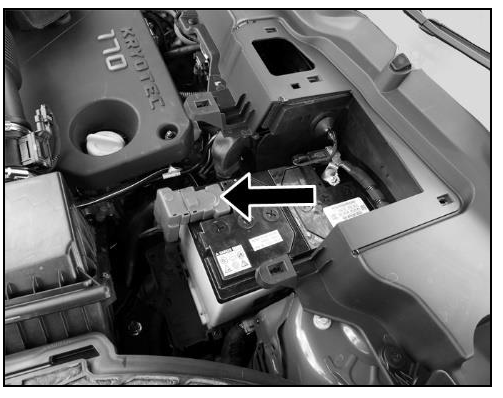

| Fuse No. | Function | Fuse Rating |
| PF1 | STARTER MOTOR | 250 A |
WARNING
If Fuse box cover is removed for any reason, it should be refitted properly at its original position.
Engine compartment fuse box
Fuse box located in Engine compart-ment near battery.
NOTE
The fuse box layout is for reference purpose only. Please refer the
sticker provided inside the fuse box cover.
To access the fuse box, follow the proce-dure as given below:
- Open the Engine compartment.
- Remove the 2 screws of air intake cover (snorkel) with the help of screw driver provided in tool kit

Fuse box located in Engine compartment near battery.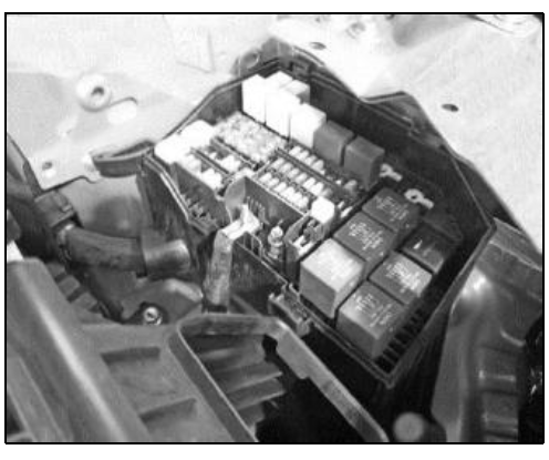
NOTE
The fuse box layout is for reference purpose only. Please refer the sticker provided inside the fuse box cover.
Fuses – Engine Compartment (Diesel)
| Fuse No. |
Function | Fuse Rating |
| 1 | INTERIOR F/B BAT – I | 60 A |
| 2 | EMS BATT | 5 A |
| 3 | COMPRESSOR | 10 A |
| 4 | SPARE | — |
| 5 | HORN HIGH/LOW TONE |
15 A |
| 6 | ABS ECU | 25 A |
| 7 | SPARE | — |
| 8 | EMS RELAY | 40 A |
| 9 | BRAKE LAMP | 5 A |
| 10 | FUEL PUMP | 20 A |
| 11 | SPARE | — |
| 12 | SPARE | — |
| 13 | SPARE | — |
| 14 | INTERIOR F/B BAT – II | 60 A |
| 15 | GLOW PLUG | 60 A |
| 16 | IGNITION LOAD | 30 A |
| 17 | ABS ECU | 40 A |
| 18 | COOLING FAN LOW | 40 A |
| 19 | STARTER MOTOR SOL |
30 A |
| 20 | BLOWER MOTOR | 40 A |
| 21 | COOLING FAN FAST | 60 A |
| 22 | UNDERBONNET F/R BOX | 30 A |
| 23 | SPARE | — |
| 24 | HEAD LAMP HIGH BEAM RH |
10 A |
| 25 | HEAD LAMP HIGH BEAM LH |
10 A |
| 26 | HEAD LAMP LOW BEAM RH | 10 A |
| 27 | HEAD LAMP LOW BEAM LH | 10 A |
| 28 | EMS ECU – II | 15 A |
| 29 | EMS ECU – I | 20 A |
| 30 | EMS ECU – III | 10 A |
| 39 | SPARE | — |
| 40 | EMS IGN | 5 A |
| 41 | ABS IGN | 5 A |
| 42 | REVERSE LAMP | 5 A |
| 43 | FRONT WIPER MO- TOR | 30 A |
| 44 | SPARE | — |
| 45 | SPARE | — |
| 46 | SPARE | — |
| 47 | EMS-CRANK INPUT | 5 A |
| Relay No. | Relay Function | Relay Rating |
| R1 | IGNITION MINI NO RELAY | 40A |
| R2 | COOLING FAN LOW MINI NO RELAY | 40A |
| R3 | COOLING FAN HIGH MAXI NO RELAY | 70A |
| R4 | EMS ECU MINI NO RELAY | 40A |
| R5 | STARTER SOLENOID MINI NO RELAY | 40A |
| R6 | STARTER INHIBIT MINI NO RELAY | 40A |
| R7 | — | |
| R8 | — | |
|
R9 |
WIPER SPEED
SLOW/FAST MICRO (NO-NC) RELAY |
20A |
| R10 | — | |
| R11 | WIPER ON/OFF MI- CRO (NO-NC) RELAY | 20A |
| R12 | ATS MICRO NO REALY | 20A |
|
R13 |
HEAD LAMP HIGH BEAM MICRO NO REALY |
20A |
| R14 | DCU MICRO NO RE- LAY | 20A |
|
R15 |
HEAD LAMP LOW
BEAM MICRO NO REALY |
20A |
| R16 | HORN MIRCO NO
RELAY |
20A |
| R17 | FUEL PUMP MICRO NO RELAY | 20A |
| R18 | AC CLUTCH MICRO NO REALY | 20A |
Cabin compartment fuse box
Cover removal procedure Fuse box is located behind glove box. To access the fuse box, remove cover as per procedure given below:
- Remove snap fitted end-cover first.

- To remove the cover, gently pull the cover from bottom side such that the lugs get disengaged.

- Open glove box and remove complete assembly by removing high-lighted 4 screws.

- Disconnect glove box lamp connection.

5. Disconnect glove box switch connection.
6. Pull out the fuse from fuse box modules from available cutout as shown below.
7. Check the fuse of required function with help of fuse box sticker present at shown location.
8. If fuse is blown, replace with same rating fuse from spare fuses in en-gine compartment fuse box.
9. Fit back the glove box by following re-verse procedure.
NOTE
It is recommended to replace fuse at TATA Authorised service centre.
Fuses – Cabin Compartment
| Fuse Function | Fuse Rating |
| IGN SUPPLY | 10A |
| POWER SOCKET | 15A |
| RESTRAINT CONTROL MUDULE | 10A |
| MIRROR ADJUST MOTOR | 5A |
| IMMO IGN/ PEPS IGN FEED- BACK | 5A |
| USB CHARGER BSIV/ USB CHARGER BSVI | 5A/ 10A |
| RELAY COIL/ PEPS ACC | 10A/ 5A |
| ACC BATT HIGH POWER | 20A |
| BCM – I | 15A |
| IMMO BATT/ TPMS BATT | 5A |
| BCM – II | 15A |
| INFOTAINMENT | 20A |
| BCM – III | 15A |
| OBD/ ACC BATT LOW POWER | 15A |
| HVAC BAT | 10A |
| AMPLIFIER | 20A |
| PEPS | 10A |
| I. CLUSTER | 5A |
| KEY-IN/ POWER SEAT | 5A/ 20A |
| ACC RELAY COIL/ SUN- ROOF | 5A/ 20A |
| TERRAIN RESPONSE SWITCH | 10A |
| TRANSIT | 10A |
| REAR WIPER | 10A |
| REAR BLOWER MOTOR | 15A |
| PARK ASSIST | 5A |
| W/W MTR DR DOOR | 25A |
| USB CHARGER 3RD ROW | 5A |
| CDL | 15A |
| STARTER FEEDBACK | 5A |
| HRW | 25A |
| SUNSHADE/ BLOWER CON- TROLLER | 20A/ 5A |
| TAILGATE RELEASE | 10A |
| CDL – LOCK
MICRO NO-NC RELAY |
20A |
| CDL – UNLOCK MICRO NO-NC RELAY | 20A |
| TAILGATE RELEASE MICRO NO RELAY | 20A |
| IGNITION
MICRO NO RELAY |
20A |
| REAR WIPER MICRO NO RELAY | 20A |
| POWER SEAT MICRO NO RELAY | 20A |
| REVERSE LAMP MICRO NO RELAY | 20A |
| HEATED REAR WINDOW MINI NO RELAY | 40A |
| BLOWER MOTOR MINI NO RELAY | 40A |
| ACCESSORY MINI NO RELAY | 40A |
How to Replace the Fuses of the Tata Harrier BSVI
Replacing a fuse in your Tata Harrier BSVI is a straightforward process that ensures the proper functioning of your vehicle’s electrical components. Here’s a step-by-step guide to help you through the process:
Materials:
- The new fuse of the correct amperage.
- Fuse puller or needle-nose pliers.
Steps to Replace a Fuse
-
Ensure Safety:
-
Apply the parking brake.
-
Switch off all electrical accessories.
-
Turn the ignition key to the ‘LOCK’ position.
-
-
Locate the Fuse Box:
-
Engine Compartment Fuse Box: Located near the battery.
-
Cabin Compartment Fuse Box: Located behind the glove box
-
-
Identify the Blown Fuse:
-
Use the fuse box diagram to locate the specific fuse.
-
A blown fuse will have a melted wire inside.
-
-
Remove and Replace the Fuse:
-
Use the fuse puller provided in the engine compartment fuse box to remove the blown fuse.
-
Replace it with a new fuse of the same rating.
-
-
Reassemble:
-
Ensure all fuses are firmly in place.
-
Reattach any covers or panels removed during the process.
-
Useful Links:
View Full PDF: Tata Harrier BSVI User Manual |Auto User Guide
Tata Harrier BSVI Instrument Cluster User Guide
Tata Harrier BSVI Automatic Transmission User Guide