Dacia Duster 2022 Lights and Indicators User Manual
Practical Advice
Tools
Accessing the tools
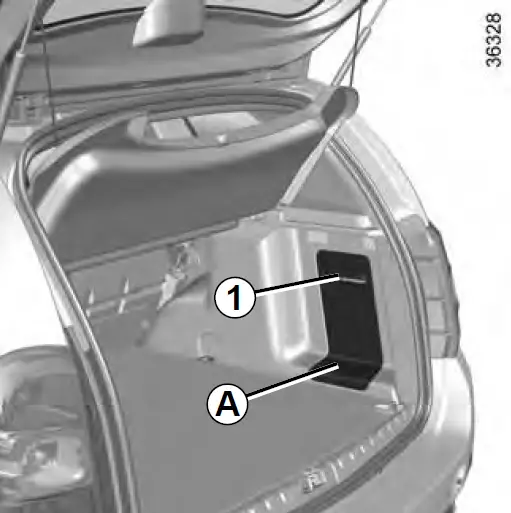
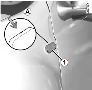
The tools are located in the luggage compartment. The presence of the various tools depends on the vehicle.
Unclip the flap A by placing your hand in the handle 1. Remove the flap.
After the using the tools, make sure you close the flap A. properly.
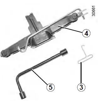
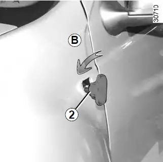
Jack 4
To use the jack, undo nut 2. When refit-ting, fold the jack before placing it in its housing.
Tighten the nut to secure the jack.

Wheelbrace 5
This is used to tighten/loosen the wheel bolts and, depending on the vehicle, to access the emergency spare wheel.
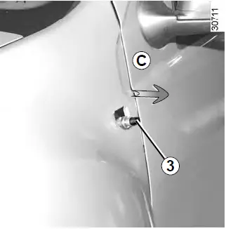
Hubcap tool 3
This tool is used to remove the wheel trims.
Do not leave the tools unsecured inside the vehicle as they may come loose under braking. After use, make sure the tools are correctly positioned in their housings: risk of injury.
If wheel bolts are supplied in the tool kit, only use these bolts for the emergency spare wheel: refer to the label affixed to the emergency spare wheel. The jack is designed for wheel changing purposes only. Under no circumstances should it be used for carrying out repairs underneath the vehicle or to gain access to the underside of the vehicle.
PUNCTURE
In the event of a puncture, depending on the vehicle, you will have:
An emergency spare wheel or tyre inflation kit (refer to the information on the following pages).
If the emergency spare wheel has been stored for several years, have it checked by your Dealer to ensure that it is safe to use.
Emergency spare wheel 4×2 version (2WD)
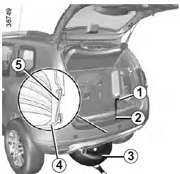
This is placed in cage 4 underneath the vehicle.
To take out the emergency spare wheel:
- Open the tailgate;
Undo bolt 2 using wheelbrace 1 (refer to the information on “Tools” in this section);
Detach the cage using handle 5;
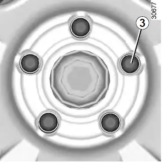
Remove emergency spare wheel 3;
Turn the emergency spare wheel over and unclip protector 6.
To store the wheel in the cage:
- Clip protector 6 onto the punctured wheel;
Turn the punctured wheel over and slide it into cage 4;
Reattach the cage using the handle 5 and retighten the nut using the wheel brace 1 to refit the assembly; - Make sure it is correctly locked.

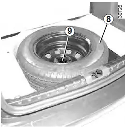
Emergency spare wheel 4×4 version (4WD)
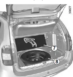
This is located in the luggage compartment.
To access it:
- Open the tailgate;
Fold back the boot mat 7;
Unscrew the central mounting 9;
Remove the emergency spare wheel 8.
Note: ensure that the emergency spare wheel or punctured wheel and the wheel tray are correctly positioned so that the luggage compartment carpet can be properly fitted.
 If the emergency spare wheel has been stored for several years, have it checked by your Dealer to ensure that it is safe to use.
Vehicles fitted with an emergency spare wheel which is different to the four other wheels:
- Never fit more than one emergency spare wheel to the same vehicle.
Replace the emergency spare wheel as soon as possible with a wheel identical to the original one.
When this is fitted to the vehicle, which must only be a temporary measure, the driving speed must not exceed the speed indicated on the label on the wheel.
Fitting an emergency spare wheel may alter the way the vehicle usually runs. Avoid sudden acceleration or deceleration and reduce your speed when cornering.
If you need to use snow chains, fit the emergency spare wheel to the rear axle and check the tyre pressure.
TYRE INFLATION KIT
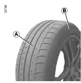
The kit repairs tyres when tread A has been damaged by objects smaller than 4 mm. It cannot repair all types of puncture, such as cuts larger than 4 mm, or cuts in tyre sidewall B.
Ensure also that the wheel rim is in good condition.
Do not pull out the foreign body causing the puncture if it is still in the tyre.
Do not attempt to use the inflation kit if the tyre has been damaged as a result of driving with a puncture.
You should therefore carefully check the condition of the tyre sidewalls before any operation.
Driving with underinflated, flat or punctured tyres can be dangerous and may make the tyre impossible to repair.
This repair is temporary
A tyre which has been punctured should always be inspected (and re-paired, where possible) as soon as possible by a specialist.
When replacing a tyre repaired using this kit, you must inform the specialist. When driving, vibration may be felt due to the presence of the repair product injected into the tyre.
The kit is only approved for inflating the tyres of the vehicle initially fitted with the kit. It must never be used to inflate the tyres of another vehicle, or any other inflatable object (rubber ring, rubber boat, etc.).
Avoid spillage on skin when handling the repair liquid bottle. If droplets do leak out, rinse them off with plenty of water.
Keep the repair kit away from children.
Do not dispose of the empty bottle in the countryside. Return it to your approved dealer or to a recycling organization.
The bottle has a limited service life which is indicated on its label. Check the expiry date.
Contact an approved dealer to re-place the inflation tube and repair product bottle.
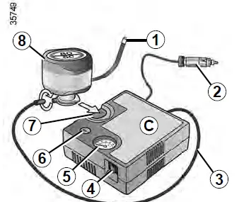
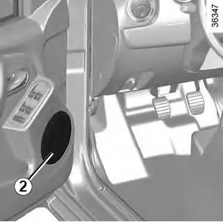
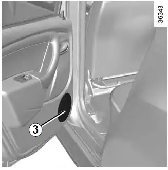
- In the event of a puncture, use the kit C located in the luggage compartment on 4×2 versions or in the emergency spare wheel tray under the luggage compartment carpet on 4×4 versions.
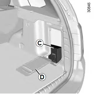
- On 4×2 versions, unclip flap D.
- Before using this kit, park the vehicle at a sufficient distance from traffic, switch on the hazard warning lights, apply the handbrake, ask all passengers to leave the vehicle and keep them away from traffic.
If the vehicle is parked on the hard shoulder, you must warn other road users of your vehicle’s presence with a warning triangle or with other devices as per the legislation applying to the country you are in.
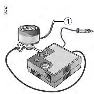
With the engine running and the par-king brake applied,
- Unroll the hose from the container;
Connect the compressor hose 3 to the container’s inlet 8;
Depending on the vehicle, connect the container 8 to the compressor from the container recess 7;
Unscrew the valve cap on the relevant wheel and screw on the container’s inflation adapter 1;
Adapter 2 must be connected to the vehicle accessories socket;
Press switch 4 to inflate the tyre to the recommended pressure (please refer to the information in the section on “Tyre pressure”);
After a maximum of 15 minutes, stop inflating and read the pressure (on pressure gauge 5).
Note: while the container is emptying (approximately 30 seconds), the pressure gauge 5 will briefly indicate a pressure of up to 6 bar. The pressure will then drop. - Adjust the pressure: to increase it, continue inflation with the kit; to reduce it, press button 6.
If a minimum pressure of 1.8 bar is not reached after 15 minutes, repair is not possible; do not drive the vehicle but contact an approved dealer.
Nothing should be placed around the driver’s feet as such objects may slide under the pedals during sudden braking maneuver’s and obstruct their use.
Please be aware that a poorly tightened or missing valve cap can make the tyres less airtight and lead to pressure loss. Always use valve caps identical to the original ones and ensure they are tightly screwed on.
Once the tyre is correctly inflated, remove the kit: slowly unscrew the inflation adapter 1 to prevent any repair product from escaping and store the container in plastic packaging to prevent the product from escaping.
- Affix the driving recommendation label to the dashboard where it can easily be seen by the driver;
Put the kit away.
At the end of this initial inflation operation, air will still escape from the tyre. You must drive a short distance in order to seal the hole. - Start immediately and drive at between 12 and 40 mph (20 and 60 km/h) in order to distribute the product evenly in the tyre and, after driving for 2 miles (3 km), stop and check the pressure.
If the pressure is greater than 1.3 bar but less than the recommended pressure (refer to the label affixed to the edge of the driver’s door), read-just it. Otherwise, please contact an authorized dealer: the tyre cannot be repaired.
Precautions when using the kit
The kit should not be operated for more than 15 consecutive minutes.
Following repair with the kit, do not travel further than 120 miles (200 km). In addition, reduce your speed and under no circumstances exceed 48 mph (80 km/h). The sticker, which you must affix in a prominent position on the dashboard, reminds you of this.
Depending on the country or local legislation, a tyre repaired with the inflation kit may need to be replaced.
WHEEL TRIM/WHEELS
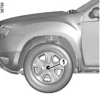
Central wheel trim with visible wheel bolts (example: wheel trim 1)
The bolts are directly accessible.
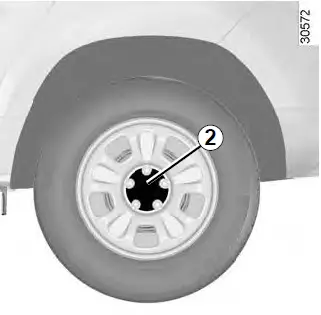
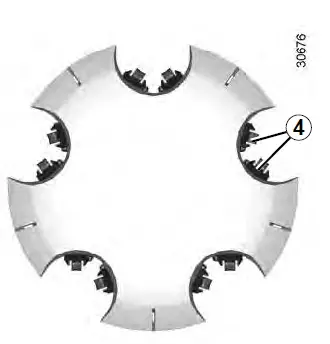
Central wheel trim with visible wheel bolts (example: wheel trim 2)
Remove it using the hubcap tool, by inserting the hook near a wheel bolt.
To put it back, position hooks 4 in relation to bolts 3.
Push in the wheel trim’s retaining hooks.
CHANGING A WHEEL
Switch on the hazard warning lights.
Park the vehicle away from traffic on flat ground with a good level of grip. Engage the hand-brake and put into gear (first or reverse).
Ask the passengers to leave the vehicle and to keep away from traffic.
 Vehicles equipped with a jack and wheelbrace
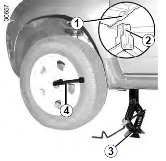
If necessary, remove the wheel trim, refer to the information on “Wheel trims – Wheels” in this Section. Undo the wheel bolts using wheel brace 4. Fit it so that you press downwards rather than pulling upwards.
To prevent any risk of injury or damage to the vehicle, only crank the jack until the wheel you are replacing is a maximum of 3 centimeters’ off the ground.
Mark hole 1, which is the nearest to the wheel in question. The jack must be fitted in this location. Offer up jack 3 horizontally and position jack head 2 under the sill.
Start cranking the jack up by hand to align the base plate (which should be pushed slightly under the vehicle). Turn the wheelbrace until the wheel lifts off the ground.
Remove the bolts.
Take off the wheel.
Fit the emergency spare wheel on the central hub and turn it to align the mounting holes in the wheel and the hub.
If the vehicle is parked on the hard shoulder, you must warn other road users of your vehicle’s presence with a warning triangle or with other devices as per the legislation applying to the country you are in.
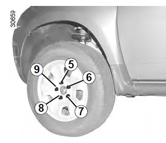
Tighten the bolts, checking that the wheel is correctly positioned on its hub and lower the jack.
With the wheels on the ground, tighten the bolts firmly, beginning on side 5, then 7, 9, 6, and finishing with 8. Check the tightness (tightening torque 105 Nm), and the pressure of the emergency spare wheel’s tyre as soon as possible.
If the vehicle is not equipped with a jack or wheelbrace, you can obtain these from your approved dealer.
Note: ensure that the emergency spare wheel or punctured wheel and the wheel tray are correctly positioned so that the luggage compartment carpet can be properly fitted.
If the vehicle is parked on the hard shoulder, you must warn other road users of your vehicle’s presence with a warning triangle or with other devices as per the legislation applying to the country you are in.
TYRES
Tyre and wheel safety
The tyres are the only contact between the vehicle and the road, so it is essential to keep them in good condition.
You must make sure that your tyres conform to local road traffic regulations.
When they need to be re-placed, only tyres of the same make, size, type and profile should be used.
Tyres fitted to the vehicle should either be identical to those fitted originally or conform to those recommended by your approved dealer.
Maintaining the tyres
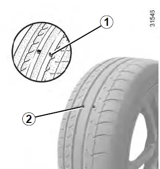
The tyres must be in good condition and the tread form must have sufficient depth; tyres approved by our Technical Department have wear warning strips 1 which are indicators moulded into the tread at several points.
When the tyre tread has been worn to the level of the warning strips, they become visible 2: it is then necessary to replace your tyres because the tread rubber is now only 1.6 mm deep at most, resulting in poor road holding on wet roads.
An overloaded vehicle, long journeys by motorway, particularly in very hot weather, or continual driving on poorly surfaced minor roads will lead to more rapid tyre wear and affect safety.
Incidents which occur when driving, such as striking the kerb, may damage the tyres and wheel rims, and could also lead to misalignment of the front or rear axle geometry. If such incidents occur, have the condition of these parts checked by an approved dealer.
Tyre pressures
Adhere to the tyre pressures (including the emergency spare wheel). The tyre pressures should be checked at least once a month and additionally before any long journey (refer to the label affixed to the edge of the driver’s door).
Incorrect tyre pressures lead to abnormal tyre wear and unusually hot running. These are factors which may seriously affect safety and lead to:
- Poor road holding;
Risk of blowouts or throwing a tread.
The tyre pressure depends on the load and speed of use; adjust the pressures according to the conditions of use (refer to the information on “Tyre pressures” in Section 4).
Pressures should be checked when the tyres are cold; ignore higher pressures which may be reached in hot weather or following a fast journey.
If tyre pressures cannot be checked when the tyres are cold, assume an in-crease of 0.2 to 0.3 bar.
Never deflate a hot tyre.
Special note
Depending on the vehicle, there may be an adapter which needs to be positioned on the valve before air is added.
Your vehicle is equipped with large wheels. These are more sensitive to imbalance. If you experience vibration while driving, contact an approved dealer.
Fitting new tyres
For safety reasons, this operation must be carried out by a specialist.
Fitting different tyres may change your vehicle as follows:
It may mean that your vehicle no longer conforms to current regulations;
It may change the way it handles when cornering;
It may cause the steering to be heavy;
It may affect the use of snow chains.
Emergency spare wheel
Refer to the information on the “Emergency spare wheel” and “Changing a wheel” in Section 5.
Please be aware that a poorly tightened or missing valve cap can make the tyres less airtight and may lead to pressure loss. Always use valve caps of the same type as the originals and tighten them fully.
 Changing wheels around
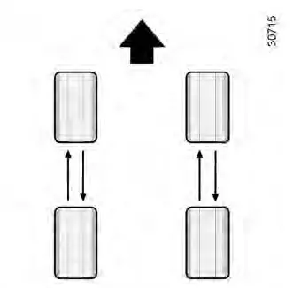
We recommend that you swap the wheels regularly in order to ensure that the tyres wear evenly.
Swap the wheels as shown in the above diagram. Refer to your vehicle’s maintenance document for the intervals.
Use in winter
Chains
2-wheel drive version (2WD)
Snow chains must be fitted to the front wheels.
4-wheel drive version (4WD)
Snow chains may be fitted to only the front wheels, or to all four wheels.
It is forbidden to fit snow chains to only the rear wheels.
Snow chains may only be fitted to tyres of the same size as those originally fitted to your vehicle.
Only certain chains can be fitted to tyres.
Consult an approved dealer.
Snow or Winter tyres
We would recommend that these be fitted to all four wheels to ensure that your vehicle retains maximum adhesion.
Warning: These tyres sometimes have a specific direction of rotation and a maximum speed index which may be lower than the maximum speed of your vehicle.
Studded tyres
This type of equipment may only be used for a limited period and as laid down by local legislation.
It is necessary to observe the speed specified by current legislation.
These tyres must, at a minimum, be fitted to the two front wheels.
In all cases, we would recommend that you contact your approved dealer who will be able to advise you on the choice of equipment which is most suitable for your vehicle.
FRONT LIGHTS: Changing Bulbs
The bulbs detailed below can be re-placed. However, we recommend that these be replaced by an approved dealer if this proves difficult.
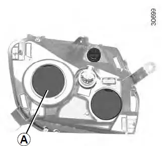
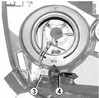
Dipped beam headlights
Remove cover A.
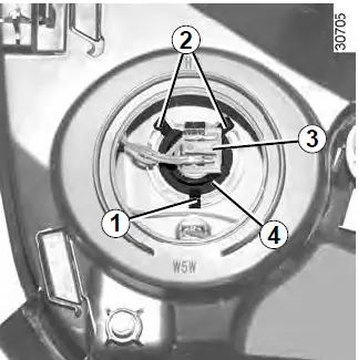
Unclip bulb 4 by pressing connector 3 downwards to release the bulb from clips 2 and 1.
Do not touch the bulb glass. Hold it by its base.
It is essential to use anti-UV bulbs so as not to damage the plastic on the headlights.
Remove bulb 4 from connector 3.
Bulb type: H7
Once the bulb has been replaced, be sure to correctly reposition lug 5 in notch 6, then refit cover A.
The bulbs are under pressure and can break when replaced.
Risk of injury.
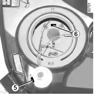
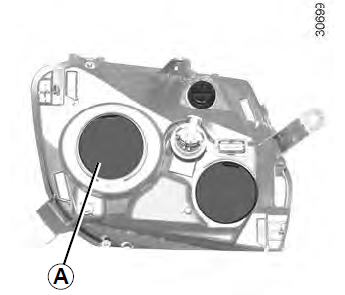
Front side light
Remove cover A.
The engine may be hot during operations in close proximity. In addition, the engine cooling fan may come on at any moment. Risk of injury.
The engine may be hot during operations in close proximity. In addition, the engine cooling fan may come on at any moment. Risk of injury.
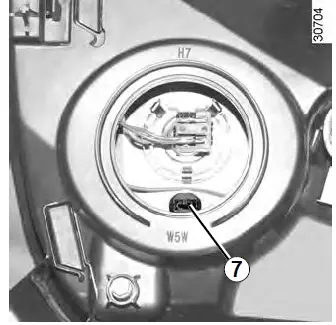
Remove bulb holder 7.
The bulbs are under pressure and can break when replaced.
Risk of injury.
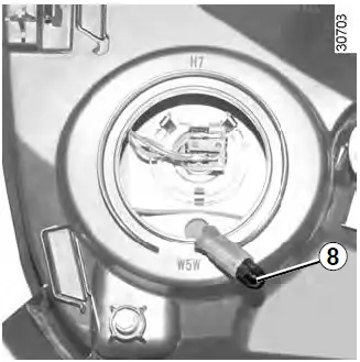
Remove bulb 8.
Bulb type: W5W.
When the bulb has been changed, make sure you refit cover A correctly.
To comply with local legislation, or as a precaution, you can obtain an emergency kit containing a set of spare bulbs and fuses from an approved dealer.
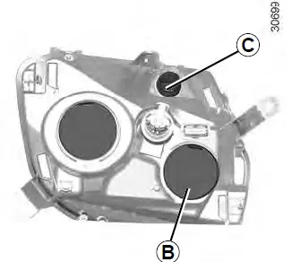
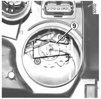
Main beam headlights
Remove cover B.
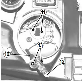
Release spring 9 and remove bulb 12 with connector 10.
Unclip the bulb from its connector.
Bulb type: H1.
It is essential to use anti-U.V. 55W bulbs so as not to damage the plastic on the headlights.
Once the bulb has been replaced, be sure to correctly reposition the two lugs 13 in holes 11, as well as the spring and the cover. Main beam headlights
Remove cover B.
Release spring 9 and remove bulb 12 with connector 10.
Unclip the bulb from its connector. Bulb type: H1.
It is essential to use anti-U.V. 55W bulbs so as not to damage the plastic on the headlights.
Once the bulb has been replaced, be sure to correctly reposition the two lugs 13 in holes 11, as well as the spring and the cover.
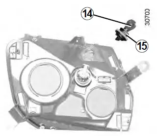
Direction indicator lights
Turn bulb holder C fully anticlockwise and remove it.
Replace bulb 14.
Bulb type: PY21W.
Once the bulb has been replaced, be sure to correctly reposition the two lugs 15 in relation to the slots in the light.
Turn the bulb holder fully clockwise.

Dipped beams
Remove the cover D.
Tilt the bulb holder 20 to release it and then replace the bulb.
Bulb type: H7.
The bulbs are under pressure and can break when replaced.
Risk of injury.
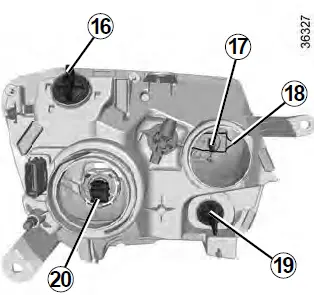
Main beam headlight
Remove the cover E.
Remove the bulb connector 17. Unclip the spring 18 and take out the bulb.
Bulb type: H1.
It is essential to use anti-U.V. 55W bulbs so as not to damage the plastic on the headlights.
Do not touch the bulb glass. Hold it by its base.
Mark the bulb’s position before removal to ensure correct positioning when replacing.
When the bulb has been changed, make sure you refit the cover correctly.
Daytime running light, front side light
Turn the bulb holder a quarter of a turn 16 and take out the bulb.
Bulb type: W21/5W.
Direction indicator lights
Turn the bulb holder 19 a quarter of a turn and take out the bulb.
Bulb type: PY21W.
To comply with current legislation, or as a precaution, you can obtain an emergency kit from your approved dealer containing a set of spare bulbs and fuses.
The engine may be hot during operations in close proximity. In addition, the engine cooling fan may come on at any moment. Risk of injury.
FOG LIGHTS: Changing Bulbs
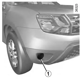
Front fog lights 1
Consult an approved dealer. Bulb type: H16 or depending on vehicle, H11.
The bulbs are under pressure and can break when replaced.
Risk of injury.
Additional lights
If you wish to fit fog lights to your vehicle, please see an authorized dealer.
Any operation on (or modification to) the electrical system must be performed by an approved Dealer since an incorrect connection might damage the electrical equipment (harness, components and in particular the alternator). In addition, your Dealer has all the parts required for fitting these units
To comply with local legislation, or as a precaution, you can obtain an emergency kit containing a set of spare bulbs and fuses from an ap-proved Dealer.
The engine may be hot during operations in close proximity. In addition, the engine cooling fan may come on at any moment. Risk of injury.
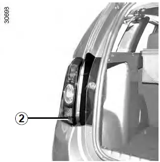
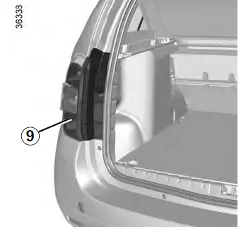
REAR LIGHTS: Changing Bulbs
Rear lights
Open the tailgate and unscrew the nuts 1, then release the light unit 2 by pulling it out.
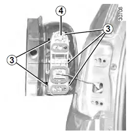
Release the clips 3 to remove the bulb holder 4.
Side light and brake light
Pear-shaped, bayonet type bulb with two P 21/5 W filaments.
Direction indicator light
Pear-shaped, bayonet type P 21 W or PY 21 W bulb (depending on vehicle).
Reversing light
Pear-shaped bayonet bulb P 21 W or,
Rear fog light (depending on vehicle)
Pear-shaped, bayonet type P 21 W bulb.
Refitting
To refit, proceed in the reverse order, taking care not to damage the wiring.
The bulbs are under pressure and can break when replaced.
Risk of injury.
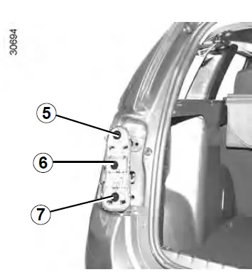
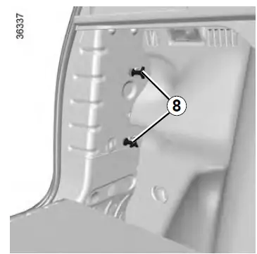
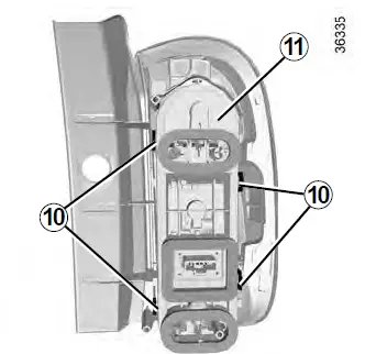
Open the tailgate and unscrew the nuts 8, then release the light unit 9 by pulling it out.
Release the clips 10 to remove the bulb holder 11.
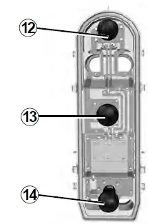
Side light and brake light
Pear-shaped, bayonet type bulb with two P 21/5 W filaments.
Direction indicator lights
Pear-shaped, bayonet type P 21 W or PY 21 W bulb (depending on vehicle).
Reversing light
Pear-shaped bayonet bulb P 21 W or,
Rear fog light
(depending on vehicle)
Pear-shaped, bayonet type P 21 W bulb.
Refitting
To refit, proceed in the reverse order, taking care not to damage the wiring.
The bulbs are under pressure and can break when replaced.
Risk of injury.
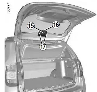
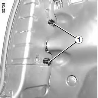
High-level brake light
The bulb for the high-level brake light 16 can be accessed through the boot. Carefully unclip the cover 15 by pressing tabs 17.
To comply with current legislation, or as a precaution, you can obtain an emergency kit from your approved dealer containing a set of spare bulbs and fuses.
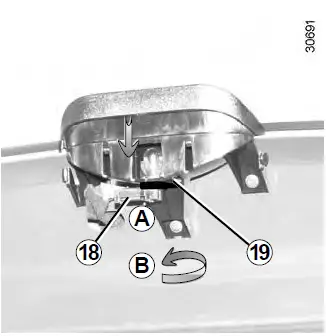
Unclip the tab 19 carefully (movement A) and turn it an eighth of a turn (movement B) to release the bulb holder 18.
The bulbs are under pressure and can break when replaced.
Risk of injury.
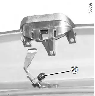
Remove the bulb20.
Bulb type: W 16 W.
TYRE INFLATION KIT
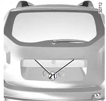
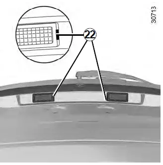
Number plate light
Unclip the light 21 by pressing tab 22 using a flat-blade screwdriver type tool.
Unclip the lens 24 and take out the bulb 23.
Bulb type: W 5 W.

INDICATOR LIGHTS: Changing Bulbs
Unclip indicator light 1 (using a flat-blade screwdriver or similar positioned at A to move the indicator light towards the outside of the vehicle).
Turn bulb holder 2 a quarter of a turn (movement B) and take out bulb 3 (movement C).
Bulb type: WY5W.
The bulbs are under pres-sure and can break when replaced.
Risk of injury.
 INTERIOR LIGHTING: Changing Bulbs

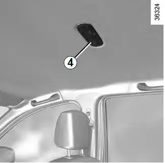
Courtesy light A
Unclip lens 1 using a flat-blade screw-driver or similar.
Remove the bulb concerned.
Bulb type 2: W5W.
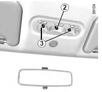
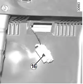
Front map reading lights
(depending on the vehicle)
Remove the lens 1 using a tool such as a flat-blade screwdriver.
Remove the bulb concerned.
Bulb type 3: W5W.
The bulbs are under pressure and can break when replaced.
Risk of injury.
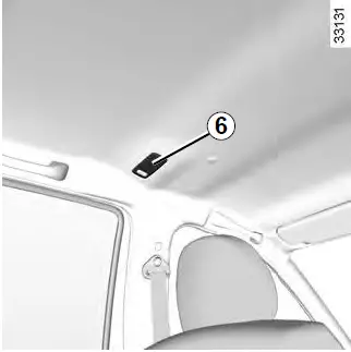
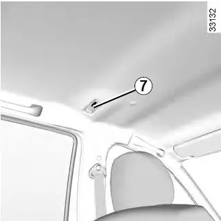
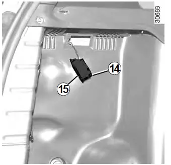
Rear map reading lights (depending on the vehicle)
Unclip the lens 4 or 6 using a flat-blade screwdriver or similar.
Remove the bulb concerned.
Bulb type 5: W5W.
Bulb type 7: C8W.

The bulbs are under pressure and can break when replaced.
Risk of injury.
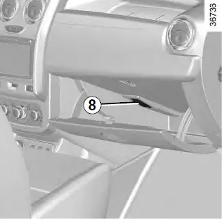
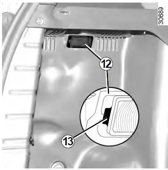
Glove box light (depending on the vehicle)
Unclip the light 8 using a flat-blade screwdriver or similar, by pressing on the tab to move the light towards the inside of the unit.
Disconnect the light.
Press the tab 9 to release the lens 11 and gain access to the bulb 10.
Bulb type 10:W5W.
The bulbs are under pressure and can break when replaced.
Risk of injury.
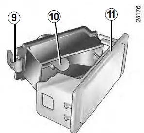
Luggage compartment light
Unclip the light 12 using a flat-blade screwdriver or similar, by pressing on the tab 13 to move the light towards the inside of the boot.
Press the tab 14 to release the lens 1
The bulbs are under pressure and can break when replaced.
Risk of injury.
Remove the bulb 16.
Bulb type 16:W5W.
FUSES
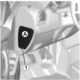
Passenger compartment fuses
If any electrical component does not work, check the condition of the fuses. Unclip flap A using notch 1 to help you. Depending on the vehicle, to identify the fuses, refer to the fuse allocation label located at the back of the flap A and shown on the following pages.
To comply with current legislation, or as a precaution, you can obtain an emergency kit from your approved Dealer containing a set of spare bulbs and fuses.
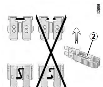
Tweezers 2
Remove the fuse using tweezers 2, located at the back of flap A.
To remove the fuse from the tweezers, slide the fuse to the side.
It is not advisable to use the free fuse locations.
Check the fuse in question and replace it, if necessary, with a fuse of the same rating.
If a fuse is fitted where the rating is too high, it may cause the electrical circuit to overheat (risk of fire) in the event of an item of equipment using an excessive amount of current.
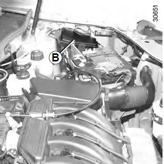
Fuses in engine compartment B
Some functions are protected by fuses located in the engine compartment (unit B).
However, because of their reduced accessibility, we advise you to have your fuses replaced by an approved dealer.
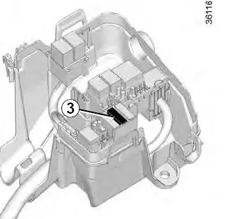
Special features of LPG versions
The specific LPG circuit shut-off fuse 3 is located in the box B.
When working in the engine compartment, ensure that the windscreen wiper stalk is in the park position.
Risk of injury.
Allocation of fuses in the passenger compartment
(the presence of certain fuses DEPENDS ON THE VEHICLE EQUIPMENT LEVEL)
FUSES (24/6)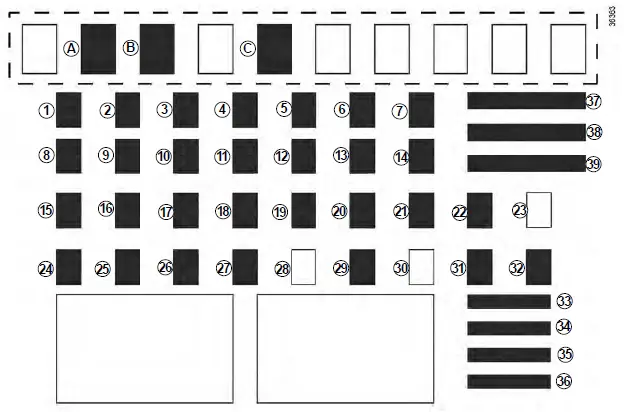
| Number | Allocation |
| A | Driver’s side window winder |
| B | 4-wheel drive (4WD) transmission |
| C | Rear accessories socket |
| 1 | Front electric window |
| 2 | Left-hand main beam headlight |
| 3 | Right-hand main beam headlight |
| 4 | Left-hand dipped beam headlight |
| 5 | Right-hand dipped beam headlight |
| 6 | Left-hand side lights |
| 7 | Right-hand side lights |
| 8 | Rear electric windows |
| 9 | Rear fog lights |
| 10 | Horn |
| 11 | Automatic door locking |
| Number | Allocation |
|
12 |
ABS-ESC, brake switch |
| 13 | Courtesy light, Boot light |
| 14 | ESC |
| 15 | Reverse gear, windscreen wiper |
| Cruise control/Speed | |
| limiter, rear-view mirror, | |
| 16 | unfastened seat belt warning, parking distance |
| control, multimedia, air | |
| conditioning | |
| 17 | Daytime running lights |
| 18 | Brake lights |
| Injection, instrument panel, | |
| 19 | passenger compartment unit |
| 20 | Airbag |
|
21 |
4-wheel drive (4WD) transmission, LPG |
| 22 | Power-assisted steering |
| 23 | Empty location |
| Number | Allocation |
| 24 | Passenger compartment ECU |
| 25 | Passenger compartment ECU |
| 26 | Direction indicator lights |
| 27 et 29 | Steering column control |
| 28 | Empty location |
| 30 | Empty location |
| 31 | Instrument panel |
| Radio, passenger | |
| 32 | compartment air conditioning control panel |
| 33 | Cigar lighter |
| 34 | Diagnostics and radio socket |
| 35 | Defrosting rearview mirror |
| 36 | Electric door mirrors |
|
37 |
Passenger compartment ECU, starter |
| 38 | Front windscreen wiper |
| 39 | Passenger compartment ventilation |
Allocation of fuses in the passenger compartment
(the presence of certain fuses DEPENDS ON THE VEHICLE EQUIPMENT LEVEL)
| Symbol | Allocation |
Stop
UCH |
ABS
Radio Brake lights Air conditioning Front fog lights Instrument panel Injection Windscreen wiper Central locking of doors and tailgate Rear screen de-icing Not used Horn Main power supply |

| Symbol | Allocation |
  |
Heated seats
Heated door mirrors Electric front windows Interior lighting Electric door mirror Heating Not used Air bag Right-hand main beam headlight Left-hand main beam headlight |
| Symbol | Allocation |
|
|
Left-hand dipped beam headlight
Right-hand dipped beam headlight Right-hand side light Left-hand side light Rear fog light Electric rear windows Engine immobiliser Reversing light and rear screen wiper Power-assisted steering |


Allocation of fuses in the passenger compartment
(the presence of certain fuses DEPENDS ON THE VEHICLE EQUIPMENT LEVEL)
| Symbol | Allocation |
|
CNG
|
Automatic gearbox GAS fuel
4-wheel drive (4WD) transmission |
To comply with current legislation, or as a precaution, you can obtain an emergency kit from your approved Dealer containing a set of spare bulbs and fuses.
Check the fuse in question and replace it, if necessary, with a fuse of the same rating.
If a fuse is fitted where the rating is too high, it may cause the electrical circuit to overheat (risk of fire) in the event of an item of equipment using an excessive amount of current.
BATTERY: Troubleshooting
To avoid all risk of sparks:
- Ensure that any consumers (courtesy lights, etc.) are switched off before disconnecting or reconnecting the battery;
When charging, stop the charger before connecting or disconnecting the battery;
to avoid creating a short circuit between the terminals, do not place metal objects on the battery;
Always wait at least one minute after the engine has been switched off before disconnecting a battery;
Make sure that you reconnect the battery terminals after refitting.
Connecting a battery charger
The battery charger must be compatible with a battery with nominal voltage of 12 volts.
Do not disconnect the battery when the engine is running. Follow the instructions given by the manufacturer of the battery charger you are using.
When many accessories are fitted to the vehicle, have them connected to the + after ignition feed.
Certain batteries may have specific recharging requirements; consult your authorized dealer. Avoid any risk of sparks, as this could cause a sudden explosion, and always charge the battery in a well-ventilated area. Risk of serious injury.
Handle the battery with care as it contains sulphuric acid, which must not come into contact with eyes or skin. If it does, wash the affected area with plenty of cold water and consult a doctor, if necessary.
Ensure that naked flames, red hot objects and sparks do not come into contact with the battery as there is a risk of explosion.
The engine may be hot during operations in close proximity. In addition, the engine cooling fan may start to operate at any moment. Risk of serious injury.
Starting the vehicle using the battery from another vehicle
If you have to use the battery from an-other vehicle to start, obtain suitable jump leads (with a large cross section) from an approved dealer or, if you al-ready have jump leads, ensure that they are in perfect condition.
The two batteries must have an identical nominal voltage of 12 volts. The battery supplying the current should have a capacity (amp-hours, Ah) which is at least the same as that of the discharged battery.
Ensure that there is no risk of contact between the two vehicles (risk of short circuiting when the positive terminals are connected) and that the discharged battery is properly connected. Switch off your vehicle ignition.
Start the engine of the vehicle supplying the current and run it at an intermediate engine speed.
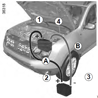
Connect the positive (+) lead A to (+) terminal 1 of the discharged battery, then to (+) terminal 2 of the battery sup-plying the current.
Connect the negative (–) lead B to (–) terminal 3 of the battery supplying the current and then to (–) terminal 4 of the discharged battery.
Start the engine as normal. As soon as it is running, disconnect leads A and B in the reverse order (4-3-2-1)
Check that there is no contact between leads A and B and that the positive lead A is not touching any metal parts on the vehicle supplying the current.
Risk of injury and/or damage to the vehicle.
RADIO FREQUENCY REMOTE CONTROL: Batteries
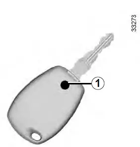
Replacing the remote control battery
Undo screw 1 to remove the remote control cover.
The batteries are available from approved Dealers, and their service life approximately two years.
Check that there is no dye on the battery: risk of an incorrect electrical contact.
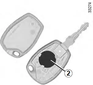
Replace battery 2 according to the direction marked on the cover.
Note: It is not advisable to touch the electronic circuit in the key cover when replacing the battery.
When refitting, ensure that the cover is correctly clipped on and the screw tightened.
Do not throw away your used batteries; give them to an organization responsible for collecting and recycling batteries.
WIPER BLADES

Replacing windscreen wiper blades 1
With the ignition off, lift wiper arm 3.
Turn the blade horizontally (movement A).
Press tab 2 and slide the wiper blade downwards (movement D) until hook 4 on the wiper arm is released.
Slide the blade (movement C) then lift it (movement B) to release it.
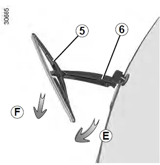
Replacing the rear screen wiper blades 5
- With the ignition off, lift wiper arm 6.
Turn blade 5 until some resistance is met (movement E).
Pull the blade to release it (movement F).
Refitting windscreen wiper blades
To refit the wiper blade, proceed in the reverse order to removal. Make sure that the blade is correctly locked in position.
Check the condition of the wiper blades. You are responsible for their service life:
- Clean the blades, windscreen and rear screen regularly with soapy water;
- Do not use them when the wind-screen or rear screen are dry;
- Free them from the windscreen or rear screen when they have not been used for a long time.
- In frosty weather, make sure that the wiper blades are not stuck by ice (to avoid the risk of the motor overheating).
- Check the condition of the wiper blades.
Replace the wiper blades as soon as they begin to lose efficiency (approximately once a year).
- Whilst changing the blade, take care not to drop the arm onto the window after it has been removed as this may break the window.
TOWING: Breakdown
Towing procedure
The steering wheel must be unlocked and the ignition key must be in position M (ignition on) to provide stop lights and hazard warning lights on the towed vehicle. Always switch on the lights when driving at night.
Unhitch the trailer, etc., if one is being towed.
You must observe the towing regulations which apply in the country in which you are driving: do not exceed the towing weight for your vehicle. Contact an approved Dealer.
When the engine is stopped, steering and braking assistance are not operational.
Do not leave the tools unsecured inside the vehicle as they may come loose under braking.

Front and rear towing points
Only use the front 1 and rear 2 towing points.
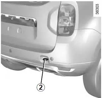
These towing points may only be used for towing: never use them for lifting the vehicle directly or indirectly.
- Use a rigid towing bar (except for off-road recovery). If a rope or cable is used (where the law allows this), the vehicle being towed must be able to brake.
A vehicle must not be towed if it is not fit to be driven. - Use a rigid towing bar (except for off-road recovery). If a rope or cable is used (where the law allows this), the vehicle being towed must be able to brake.
- A vehicle must not be towed if it is not fit to be driven.
- Avoid accelerating or braking suddenly when towing, as this may result in damage being caused to the vehicle.
- When towing a vehicle, it is advisable not to exceed 15 mph (25 km/h).
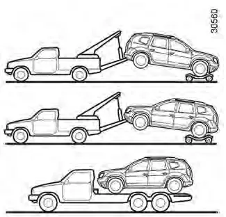
4-wheel drive vehicles (4WD)
Whichever type of gearbox is fitted, a 4WD vehicle must never be towed if any of its 4 wheels are touching the ground.
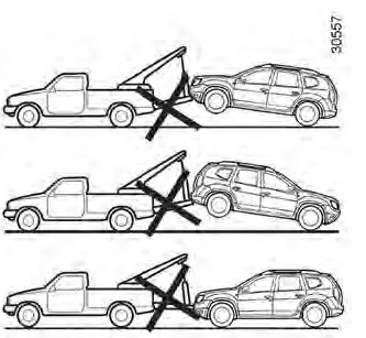
You must never tow a 4-wheel drive vehicle, irrespective of the mode selected, if one of the 4 wheels is in contact with the ground (except for off-road recovery). Risk of mechanical damage.
Off-road recovery
If your vehicle is stuck in sand, snow or mud, attach a flexible towing device (towing belt or other device specially designed for this purpose) to the front or rear towing point (refer to the in-formation on “Front and rear towing points” on the previous page).
Refer to the manufacturer’s instructions for information on how to fit and operate the equipment.
If a 4×4 (4WD) vehicle becomes stuck, it should only be towed for a short distance. Risk of mechanical damage.
For off-road recovery, it is forbidden to use a rigid bar to tow a vehicle that is stuck. Risk of mechanical damage.
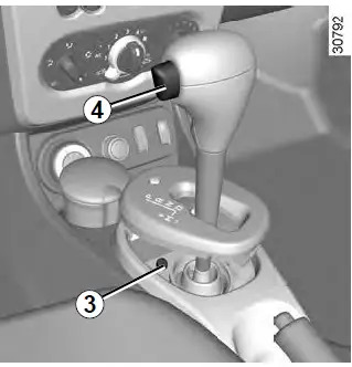
Vehicle equipped with an automatic gearbox
If the lever is stuck in P, even though you are de-pressing the brake pedal, the lever can be released manually.
To do this, unclip the cover at the base of the lever.
Simultaneously press button 3 and unlocking button 4.
When storing the tools, ensure they are securely re-placed in the luggage compartment, in their original position.
Do not leave the tools unsecured inside the vehicle as they may come loose under braking.
FITTED AUDIO EQUIPMENT
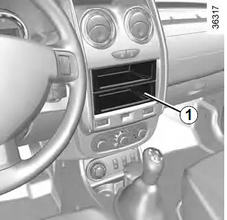
Radio location 1
If your vehicle is not fitted with an audio system, one can be fitted and locations have been provided for:
- The radio 1;
Front speakers 2;
Rear speakers 3.
To install any equipment, please consult an approved dealer.
Unclip and remove storage compartment 1.
- Location for front speaker 2 or rear speaker 3
Unclip the cover using a flat-blade screwdriver or similar.
- In all cases, it is very important to follow the manufacturer’s instructions carefully.
The specifications of the brackets and wires (available from our network) vary depending on the equipment level of your vehicle and the type of radio. Consult an authorised dealer to find out the correct part number.
No work may be carried out on the vehicle’s electrical or radio circuits, except by approved Dealers: an incorrectly connected system may result in damage being caused to the electrical equipment and/or the components connected to it.
ACCESSORIES
Electrical and electronic accessories
Before installing this type of accessory (particularly for transmitters/receivers: frequency bandwidth, power level, position of the aerial, etc.), make sure it is compatible with your vehicle. Consult an authorised dealer. Connect accessories with a maximum power of 120 Watts only. Fire hazard.
No work may be carried out on the vehicle’s electrical or radio circuits, except by authorised dealers: an incorrectly connected system may result in damage being caused to the electrical equipment and/or the components connected to it. In the case of subsequent fitting of electrical equipment, ensure that it is properly protected by a fuse. Establish the rating and position of this fuse.
Use of transmission/receiving devices (telephones, CB equipment etc.).
Telephones and CB equipment with integrated aerials may cause interference to the electronic systems originally fitted to the vehicle: it is advisable only to use equipment with an external aerial. Furthermore, we remind you of the need to conform to the legislation in force concerning the use of such equipment.
Fitting after-market accessories
If you wish to install accessories on the vehicle: please contact an authorized dealer. Furthermore, to ensure the correct operation of your vehicle, and to avoid any risk to your safety, we recommend that you use only accessories specifically designed for your vehicle, which are the only accessories for which the manufacturer will provide a warranty. If you are using an anti-theft device, only attach it to the brake pedal.
Obstructions to the driver
On the driver’s side, only use mats suitable for the vehicle, attached with the pre-fitted components, and check the fitting regularly. Do not lay one mat on top of another. There is a risk of wedging the pedals.
Special features of LPG versions
Certain LPG versions are not compatible with towbars. Please contact an authorized dealer before attempting any installation. Furthermore, to ensure the correct operation of your vehicle, and to avoid any risk to your safety, we recommend that you use only accessories specifically designed for your vehicle, which are the only accessories for which the manufacturer will provide a warranty. Any work on or modification to the LPG system which is not authorized by the car manufacturer is strictly forbidden, and if this is necessary it must be carried out by qualified personnel from an authorized dealer.
-
OPERATING FAULTS
- The following advice will enable you to carry out quick, temporary repairs. For safety reasons you should always contact an approved dealer as soon as possible.
- The starter is activated
Warning lights dim or fail to come on; the starter does not run. - POSSIBLE CAUSES
Battery terminals disconnected, oxidized or incorrectly secured. - Battery discharged or worn.
WHAT TO DO
Retighten them, reconnect them or clean them if they are oxidized.
Connect another battery to the faulty battery. Refer to the information on “Battery: troubleshooting” in Section 5 or replace the battery if necessary.
Do not push the vehicle if the steering column is locked.
Refer to the information on “Starting/stop-ping the engine in Section 2.
To unlock, gently move the key and the steering wheel (refer to the information on the “Ignition switch” in Section 2).
- On the road
- Vibrations.
- Coolant boiling in the coolant reservoir.
- Smoke under the bonnet.
The oil pressure warning light comes on: - on a bend or under braking at idle speed
- The oil pressure warning
light takes a long time to go out or remains lit during acceleration
POSSIBLE CAUSES WHAT TO DO
- Tyres not inflated to correct pressures, incorrectly balanced or damaged.
- Mechanical fault: cylinder head
- gasket damaged, faulty coolant pump
- Engine cooling fan not working
- Short circuit or cooling system leak.
- The engine oil level is too low.
- Low oil pressure.
- Loss of oil pressure
WHAT TO DO
- Check the tyre pressures; if this is not the cause, have their condition checked by an approved dealer.
- Stop the engine.
Contact an approved dealer. - Contact an approved dealer.
- Stop, switch off the ignition, move away from the vehicle and contact an approved dealer.
- Top up the engine oil level (refer to the information on “Engine oil level: topping up/filling” in Section 4).
- Go to your nearest approved dealer.
- Stop the vehicle: contact an approved dealer.
On the road
- Abnormal white smoke from the exhaust
- The power-assisted steering be-comes heavy.
- The system will not switch to “2WD” or “4WD Lock” mode. “AUTO” mode remains active.
POSSIBLE CAUSES
- Mechanical fault: damaged cylinder head gasket.
- or
This is not necessarily a fault. Smoke may be caused by regeneration of the particle filter.
Belt broken. - No power-assisted steering oil
- Fault in the 4-wheel drive system.
- Fault in the 4-wheel drive system.
WHAT TO DO
- Stop the engine.
- Contact an approved dealer.
- Please refer to the information on “Special features of diesel versions” in Section 2.
- Have the belt replaced.
- For maintenance operations on the power-assisted steering, contact an authorized dealer.
Drive as soon as possible at a moderate speed to an approved dealer. The problem may be resolved by replacing the wheels.
Contact an approved dealer as soon as possible. - On the road
Whistling
The engine overheats. The coolant temperature indicator light comes on.
The oil change warning light remains lit after an oil change.
POSSIBLE CAUSES
- Roof aerial is poorly positioned.
- Engine cooling fan not working.
- Coolant leaks.
- Warning not reset after oil change.
WHAT TO DO
- Position the aerial.
- Stop the vehicle, switch off the engine and contact an approved dealer.
Stop the vehicle, switch off the engine and check the coolant reservoir: it should contain fluid. If there is no coolant, consult an approved dealer as soon as possible.
Reset the warning after changing the oil; refer to the information in the paragraph on the “On-board computer” in Section 1.
Radiator: If there is a significant lack of coolant, remember that it must never be topped up using cold coolant while the engine is very warm. After any procedure on the vehicle which has involved even partial draining of the cooling system, it must be refilled with a new mixture prepared in the correct proportions. Reminder: only products approved by the Technical Department may be used for this purpose.
- Electrical equipment
The wipers do not work.
The wiper does not stop.
Direction indicators flashing more quickly.
The direction indicators do not work.
The headlights do not switch on or off.
Traces of condensation in the lights.
POSSIBLE CAUSES
- Wiper blades stuck.
- Faulty electrical circuit.
- Faulty electrical controls.
- Blown bulb.
- Faulty electrical circuit.
- Faulty electrical circuit or control.
- This is not a fault. Traces of condensation are a natural phenomenon caused by variations in temperature.
The traces will disappear slowly once the lights are switched on.
Reference Links
View Full User Guide: Dacia Duster 2022 User Manual
Download link: https://manual-directory.com/cars/dacia/
2022 Subaru Ascent Specs, Price, Features, Mileage (Brochure)
Related Article
2024 Subaru Crosstrek Wilderness Specs, Price, Features, Mileage (Brochure)
2024 Subaru Impreza Specs, Price, Features, Mileage (Brochure)
2023 Subaru Forester Specs, Price, Features, Mileage (Brochure)
2024 Subaru Crosstrek Specs, Price, Features, Mileage (Brochure)