
![]()
2025 FORD F-650 Fuses and Fuse Box User Manual
The fuse box is a vital component that ensures electrical integrity and safety in every vehicle. This technological cornerstone serves as a defender inside the 2025 Ford F-650, carefully preserving the complex electrical systems that fuel every trip. The fuse box in the 2025 F-650, which offers peace of mind among the intricacies of contemporary driving, is the embodiment of Ford’s dedication to innovation and driver confidence, thanks to its precision engineering and unwavering durability.
2023 Ford Bronco Specs, Price, Features, Mileage (Brochure)
FORD FUSE SPECIFICATION CHART
Engine Compartment Fuse Box
WARNING: Always disconnect the battery before servicing high-current fuses.
WARNING: To reduce risk of electrical shock, always replace the cover to the power distribution box before reconnecting the battery or refilling fluid reservoirs.
The engine compartment fuse box is in the engine compartment. It has high-current fuses that protect your vehicle’s main electrical systems from overloads. If you disconnect and reconnect the battery, you need to reset some features. Replace fuses with the same type and rating.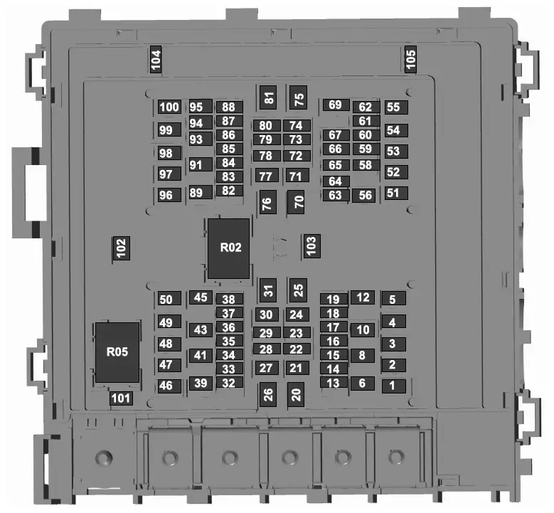
| Item | Rating | Protected Component |
| 1 | 20 A | Horn. |
| 2 | 40 A | Blower motor. |
| Item | Rating | Protected Component |
| Blower motor control. | ||
| 3 | 20 A | Upfitter – frame. |
| 4 | 30 A | Starter motor. |
| 5 | — | Not used. |
| 6 | 20 A | Upfitter relay 4. |
| 8 | — | Not used. |
| 10 | — | Not used. |
| 12 | — | Not used. |
| 13 | 10 A | Run/start spare. Rear view camera. |
| 14 | 10 A | Adaptive cruise control. |
| 15 | 10 A | Blower motor relay. |
| 16 | 20 A | Air dryer. |
| 17 | 10 A | Powertrain control module
– ignition status run power. Glow plug control module – ignition status run power (diesel). |
| 18 | 10 A | Anti-lock brake system run/ start. |
| 19 | 10 A | Transmission control module – Ignition status run power (diesel). |
| 20 | 30 A | Windshield wiper motor. |
| 21 | — | Not used. |
| 22 | — | Not used. |
| 23 | — | Not used. |
| 24 | 40 A | Body control module run power 2 bus. |
| 25 | 50 A | Body control module run power 1 bus. |
| Item | Rating | Protected Component |
| 26 | — | Not used. |
| 27 | 20 A | Upfitter battery feed. |
| 28 | — | Not used. |
| 29 | 10 A | Glow plug relay coil. |
| 30 | — | Not used. |
| 31 | 60 A | Hydromax pump. |
| 32 | 20 A | Powertrain control module. |
| 33 | 20 A | Heater exhaust gas oxygen sensor 11 (gas).
Heater exhaust gas oxygen sensor 12 (gas). Heater exhaust gas oxygen sensor 21 (gas). Canister vent solenoid (gas). Canister purge solenoid (gas). Variable camshaft timing actuator 11 (gas). Exhaust gas recirculation cooling bypass valve (diesel). |
| 34 | 10 A | A/C clutch relay (diesel). Variable oil pump (diesel). Cooling fan (diesel).
Fan clutch (gas). Exhaust brake switch (diesel). Variable oil pressure control (gas). Customer access vehicle power 3 feed. |
| 35 | 20 A | Coil on plug (gas). Nitrogen oxide sensor control module feedgas (diesel).
Nitrogen oxide sensor control module midbed (diesel). |
| Item | Rating | Protected Component |
| Nitrogen oxide sensor control module tailpipe (diesel).
Particulate matter sensor (diesel). |
||
| 36 | 10 A | Fuel volume control value (diesel).
Fuel pressure regulator (diesel). Transmission control module (diesel). |
| 37 | — | Not used. |
| 38 | — | Not used. |
| 39 | — | Not used. |
| 41 | 30 A | Trailer brake control module. |
| 43 | 30 A | Upfitter spare. |
| 45 | — | Not used. |
| 46 | 10 A | A/C clutch solenoid. |
| 47 | 40 A | Upfitter relay 1. |
| 48 | 20 A | Upfitter run and accessory feed. |
| 49 | 30 A | Pump electronics module (gas).
Fuel pump (diesel). |
| 50 | 15 A | Injector power (gas). |
| 51 | 20 A | Power point #1. |
| 52 | — | Not used. |
| 53 | 30 A | Trailer tow park lamp. |
| 54 | — | Not used. |
| 55 | 20 A | Upfitter relay 3. |
| 56 | — | Not used. |
| Item | Rating | Protected Component |
| 58 | 5 A | USB power. |
| 59 | 10 A | U-Haul parking lamps. |
| 60 | 10 A | Dual fuel tank selector switch (diesel). |
| 61 | — | Not used. |
| 62 | — | Not used. |
| 63 | 20 A | Driver seat compressor. |
| 64 | 20 A | Passenger seat compressor. |
| 65 | 10 A | Upfitter – run activate feed. |
| 66 | 10 A | Four pack solenoid differen- tial lock. |
| 67 | 10 A | Hydromax relay power. |
| 69 | — | Not used. |
| 70 | 40 A | Inverter. |
| 71 | 30 A | Anti-lock brake system valves. |
| 72 | 10 A | Brake on-off switch (hydraulic brakes). Stoplamp air pressure switch 1 and 2 (air brakes). |
| 73 | — | Not used. |
| 74 | 15 A | Heated mirror. |
| 75 | — | Not used. |
| 76 | 60 A | Body control module battery feed. |
| 77 | 30 A | Body control module voltage quality monitor power feed. |
| 78 | — | Not used. |
| 79 | 5 A | Hydromax pump monitor. |
| 80 | 10 A | Trailer tow backup signal. |
| Item | Rating | Protected Component |
| 81 | — | Not used. |
| 82 | 5 A | Upfitter switch (factory location for ignition power). |
| 83 | 5 A | Upfitter switch (optional location for power at all times). |
| 84 | — | Not used. |
| 85 | — | Not used. |
| 86 | — | Not used. |
| 87 | — | Not used. |
| 88 | 10 A | Cargo lamps. |
| 89 | 20 A | Urea tank heater. |
| 91 | 40 A | Upfitter – B-pillar. |
| 93 | — | Not used. |
| 94 | — | Not used. |
| 95 | 20 A | Stoplamps.
Trailer tow stoplamps. |
| 96 | 20 A | Urea line heater. |
| 97 | — | Not used. |
| 98 | 30 A | Trailer tow battery charge. |
| 99 | 40 A | Upfitter relay 2. |
| 100 | 20 A | Urea valves. |
| 101 | — | Not used. |
| 102 | — | Not used. |
| 103 | — | Not used. |
| 104 | — | Not used. |
| 105 | 15 A | Trailer tow stoplamp and turn relay. |
Passenger Compartment Fuse Box
The fuse panel is in the passenger footwell. Remove the panel cover to access the fuses. Pull the fuse panel cover toward you to remove it. When the clips of the panel disengage, let the panel fall easily. Use the provided fuse puller tool to remove a fuse. It is on the fuse panel cover. Replace fuses with the same type and rating. 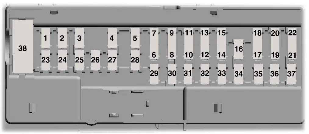
| Item | Rating | Protected Component |
| 1 | — | Not used. |
| 2 | 10 A | Right-hand and left-hand front door lock switch.
Telescopic mirror switch. Right-hand and left-hand front window switch (two window units). Right-hand and left-hand front window motor. Inverter. |
| 3 | 7.5 A | Power mirror switch. |
| 4 | 20 A | Ancillary translator module. |
| 5 | — | Not used. |
| Item | Rating | Protected Component |
| 6 | — | Not used. |
| 7 | 10 A | Smart data link connector power.
Air brake diagnostic connector. |
| 8 | — | Not used. |
| 9 | — | Not used. |
| 10 | — | Not used. |
| 11 | — | Not used. |
| 12 | 7.5 A | Smart data link connector. |
| 13 | 7.5 A | Instrument Cluster. Steering column control module. |
| 14 | — | Not used. |
| 15 | 15 A | Climate control module. |
| 16 | — | Not used. |
| 17 | — | Not used. |
| 18 | 7.5 A | Yaw sensor.
Electronic stability control and non-electronic stability control. |
| 19 | 5 A | Telematics control unit module. |
| 20 | 5 A | Ignition switch. |
| 21 | — | Not used. |
| 22 | — | Not used. |
| 23 | 30 A | Left-hand front window motor. |
| 24 | — | Not used. |
| 25 | — | Not used. |
| Item | Rating | Protected Component |
| 26 | 30 A | Right-hand front window motor. |
| 27 | — | Not used. |
| 28 | — | Not used. |
| 29 | 15 A | Relay folding mirror. |
| 30 | 5 A | Brake signal for air brake. Customer access stoplamp signal.
Brake on-off isolation relay. Trailer tow stoplamp relay. |
| 31 | 10 A | Upfitter interface module. Remote radio frequency receiver. |
| 32 | 20 A | Radio. |
| 33 | — | Not used. |
| 34 | — | Not used. |
| 35 | 5 A | Tow haul switch. |
| 36 | 15 A | Lane departure warning camera.
Mirror display. |
| 37 | — | Not used. |
| 38 | 30 A | Left-hand front power window switch (four window units). |
Note: Spare fuse amperage may vary.
CHANGING A FUSE Owner’s Manual
Fuses
WARNING: Always replace a fuse with one that has the specified amperage rating. Using a fuse with a higher amperage rating can cause severe wire damage and could start a fire.
If electrical components in the vehicle are not working, a fuse may have blown. Blown fuses are identified by a broken wire within the fuse. Check the appropriate fuses before replacing any electrical components.
Fuse Types
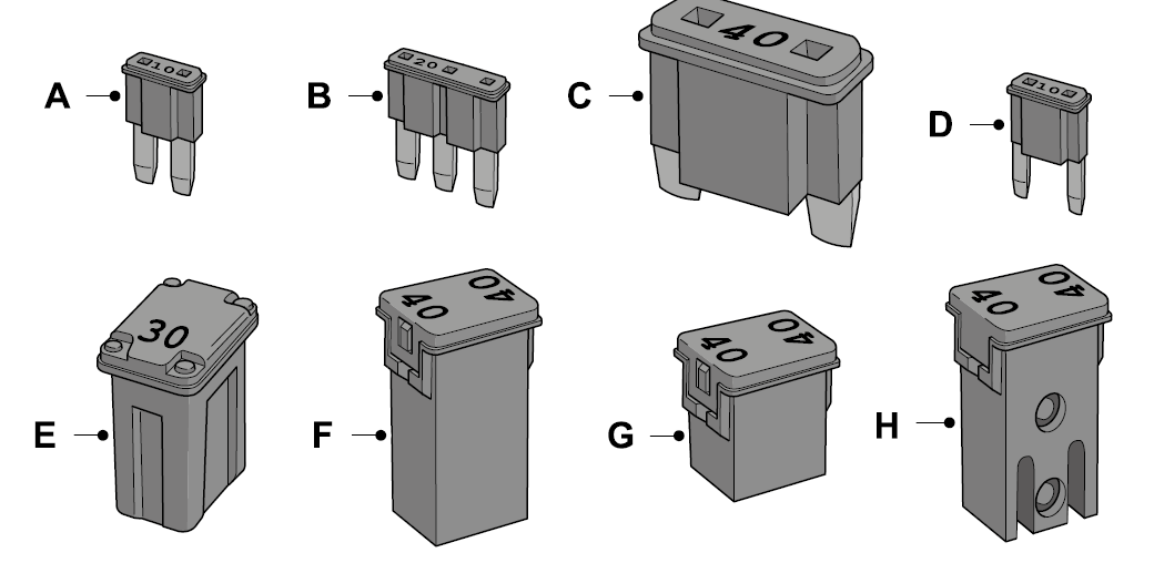
- Micro 2.
- Micro 3.
- Maxi.
- Mini.
- M Case.
- J Case.
- Case Low Profile.
- Slotted M Case.
FAQs
Fuses in the 2025 Ford F-650 protect electrical circuits from overloads by breaking the circuit when excessive current flows through them.
The 2025 Ford F-650 typically has multiple fuse boxes located in strategic positions throughout the vehicle, such as under the hood and inside the cabin.
Fuse blowouts in the 2025 Ford F-650 can occur due to various reasons, including short circuits, overloading of electrical circuits, or faulty components.
A blown fuse in the 2025 Ford F-650 can often be identified by a visible break in the metal strip inside the fuse, or by using a fuse tester to check for continuity.
When replacing fuses in the 2025 Ford F-650, drivers should ensure that the replacement fuse has the correct amperage rating and that the corresponding circuit is turned off to prevent electrical hazards.
The fuse box in the 2025 Ford F-650 typically uses standard blade-type fuses or mini fuses, depending on the electrical system’s requirements.
Accessing the fuse box in the 2025 Ford F-650 usually involves removing a cover panel located either under the hood or inside the cabin, depending on the fuse box’s location.
Yes, diagnostic tools such as multimeters or fuse testers can be used to identify fuse-related issues in the 2025 Ford F-650’s electrical system.
If drivers suspect a fuse-related issue in the 2025 Ford F-650, they should first visually inspect the fuses for signs of damage and then use diagnostic tools if necessary to pinpoint the problem.
Yes, exposure to moisture or extreme temperatures can potentially affect the functionality of the fuse box in the 2025 Ford F-650, leading to corrosion or other issues.
The fuse box in the 2025 Ford F-650 plays a crucial role in protecting the vehicle’s electrical system from damage or malfunction, thereby ensuring safe and reliable operation.
While aftermarket upgrades for the fuse box in the 2025 Ford F-650 may exist, drivers should exercise caution and ensure compatibility with their vehicle’s electrical system.
Ford employs rigorous testing and quality control measures to ensure that the fuse box in the 2025 Ford F-650 meets the highest standards of durability and longevity.
Yes, the fuse box in the 2025 Ford F-650 is designed to be easily accessible for maintenance and replacement by vehicle owners, typically requiring simple tools for removal.
The fuse box in the 2025 Ford F-650 may be integrated with the vehicle’s onboard diagnostic system, allowing for easier identification of electrical issues through diagnostic codes or alerts.
Useful Links
2023 Ford Bronco Specs, Price, Features, Mileage (Brochure)