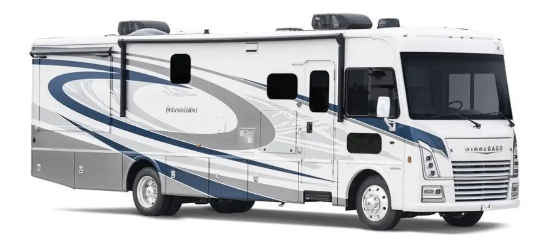
Winnebago Adventurer 2023 Connected Coach User Manual
CONNECTED COACH
Many of your motorhome’s system functions and monitoring are now conveniently observed and controlled using a LED touchscreen monitor and command center. This monitor is typically located in the central interior area of the floor plan. The following are general descriptions of the typical command screens and their functions. More detailed operational information can be found in specific functional areas within this manual.
NOTE
Each motorhome is unique in it’s specific features, equipment, systems and floor plan design, and each command center is programmed for that specific model’s configuration. As a result your motorhome’s configuration may vary somewhat from the illustrations shown here, but the basic navigation and user experience will be similar.
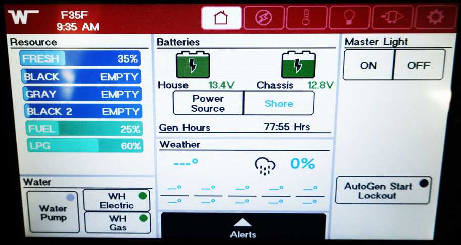
CONNECTED COACH HOME SCREEN
The Home Screen is indicated by the house shaped button located on the selector row at the top.
The Home Screen displays the fresh water and holding tank levels, propane gas tank level, as well as the chassis battery and house battery condition. You can turn on the water pump and water heater, as well as some other basic user function controls described in the following section.
Water and Holding Tank Levels
The approximate fluid levels are measured by electronic sensors on the sides of the tanks. Tank levels are displayed in 5% increments: Empty (0%), and Full (100%). There is generally more fluid in a tank than indicated on the monitor panel.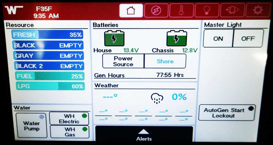
Holding tank levels on the Home Screen
-Typical View
Tank Capacities
See “Tank Capacities” in Section 1 – Introduction.
Water Pump Switch
When use of the self-contained water system is desired, turn the Water Pump switch on. The “Pump On” light will illuminate when the pump switch is on and the system is operable. Water will be available as soon as a faucet is opened. Refer to the Water Pump information elsewhere in this section for additional information on the water pump and initial start-up.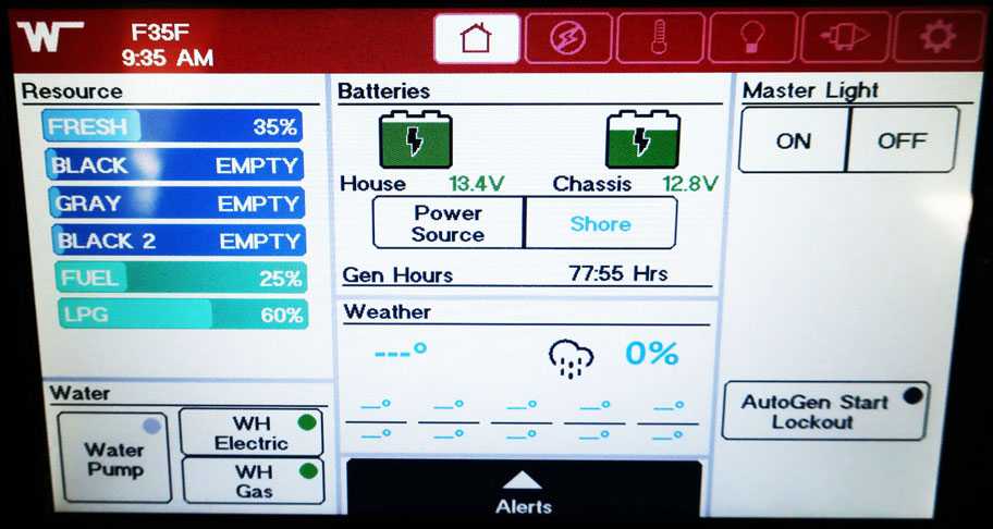
Water Pump Button
Tap Water Pump to turn off/on
-Typical View
NOTE
Some models may be equipped with a Water Pump switch in the water service center on the outside of the motorhome or within the bathroom area for your convenience.
Water Heater Controls
The water heater controls are located on the lower left of the Home Screen next to the water pump button. Press the buttons to turn off and on. Selection is between gas and electric.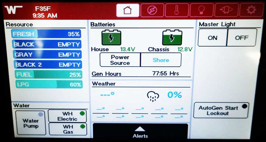
Water heater controls on the Home Screen
-Typical View
Battery Voltage
The Battery Voltage section on the Home Screen is used to monitor the House and the Engine (chassis) batteries. It also indicated the current power source being used and the total generator hours. The Auto Gen Start lockout button is located at the lower right of the home screen. Some models may display in percent of battery “state of charge” for the house battery rather than the voltage level.
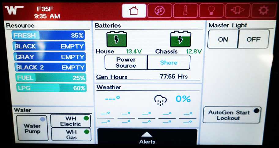
Battery Voltage section on the Home Screen
-Typical View
Weather Section
The Weather Section on the Home Screen will show the local weather and forecast (when connected to Wi-Fi or cellular service).
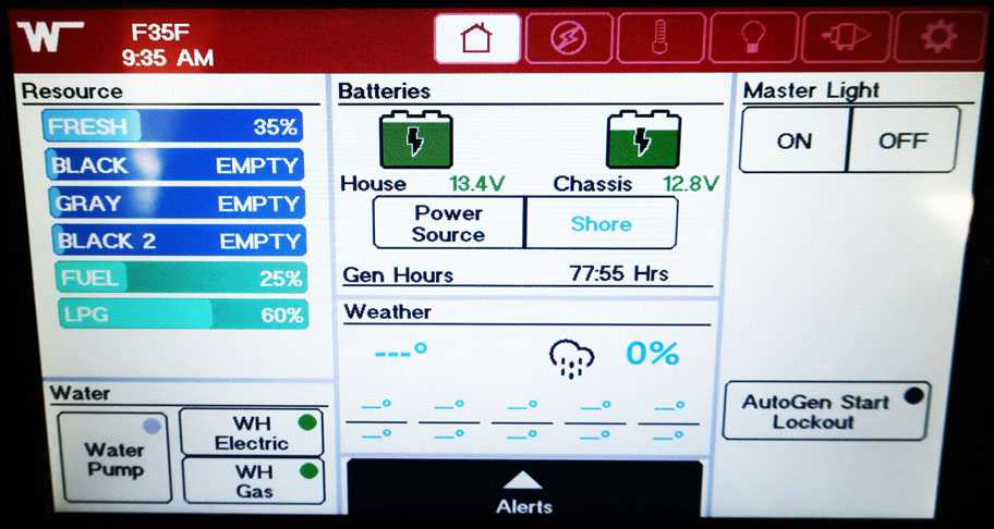 Weather section on the Home Screen
-Typical View
Light Master
The Light Master button turns on all the inside lights that are included in the master light circuitry.
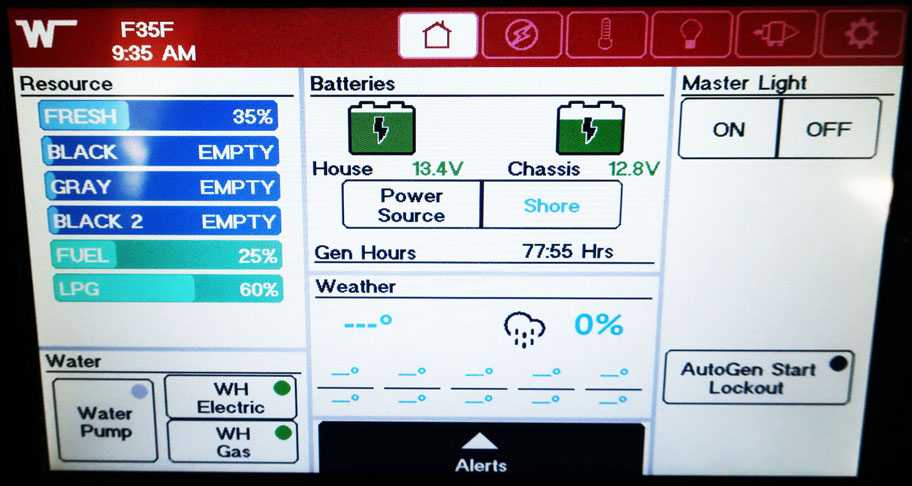
Light Master on the Home Screen
-Typical View
Alerts Viewer
The lower bottom of the Home Screen has an alerts viewer that when selected will display any trouble areas or faults. When selected the Alerts tab will raise up and the information will be displayed in the tab.
Alerts tab on the Home Screen
(Any alerts will be displayed in this space)
-Typical View
CONNECTED COACH ELECTRICAL SCREEN
The Electrical Screen is indicated by the lightning bolt shaped button located on the selector row at the top.
Electrical Main Screen
From the main screen of the electrical section you can start and stop the generator, customize generator and inverter settings, and check if shore power is connected. On the right side of the screen the individual electrical systems are listed and if they are being used are indicated by the circles.
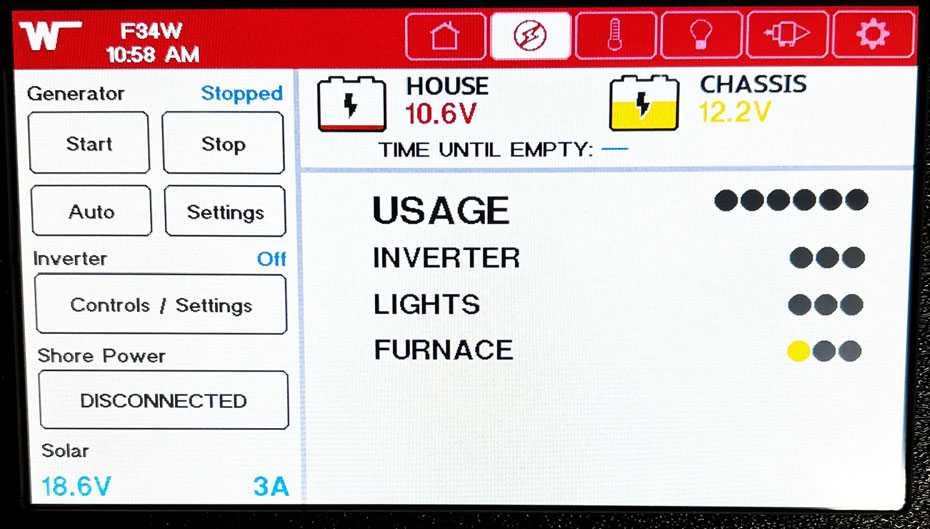
Electrical Main Screen
-Typical View
Generator Controls
The generator controls are located on the top left of the Electrical Main Screen. To start the generator hold the start button for a minimum of 1 second, the generator will start up. Press the stop button to stop the generator. The generator settings button will take you to the generator settings screen. The generator auto button will set the generator to turn on automatically according to the generator auto settings.
Further Information
Refer to the Electrical Generator section in this manual’s electrical chapter and the generator manufacturer’s user guide provided in your Info Case for complete operating instructions, specific recommendations, troubleshooting tips, safety precautions, and maintenance information.
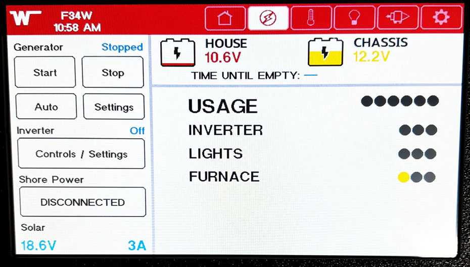
Generator Start Button
-Typical View
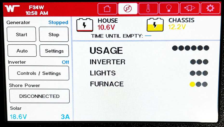
Generator Settings Button
-Typical View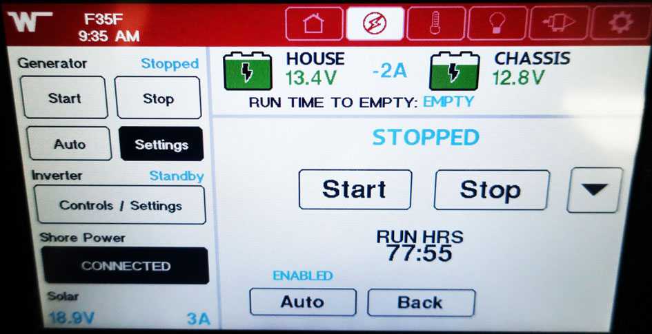
Generator Settings Screen
Use this screen to customize various triggers to automatically start and stop the generator. Select the down arrow for further customizations and options. The total run hours are also displayed on this screen Typical View.
Inverter Controls
The Inverter Controls are located on the Electrical Main Screen on the left side below the generator. This button will take you to the inverter customization including charger status, inverter status, max charge current, etc.
Further Information
See the Inverter/charger unit section in this manual’s electrical section and the inverter/charger manufacturer’s user guide provided in your Info Case for complete instructions and charging setup directions.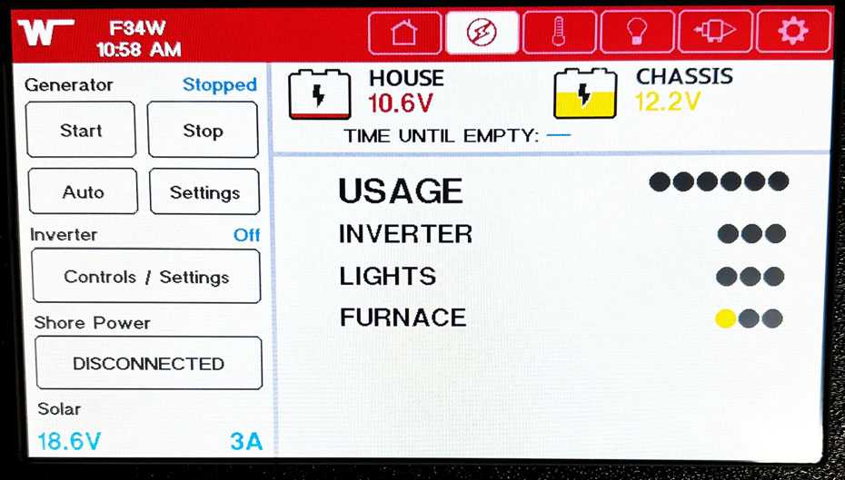
Inverter Settings Button
-Typical View
CONNECTED COACH CLIMATE SCREEN
The Climate Screen is indicated by the temperature icon button located on the selector row at the top. The Climate Screen has controls for the front and rear temperature, fan, air conditioner, and water heater controls.
Further Information
See the heating and air conditioning sections located in the Appliances chapter and the water heater section located in the Plumbing chapter of this manual for further information.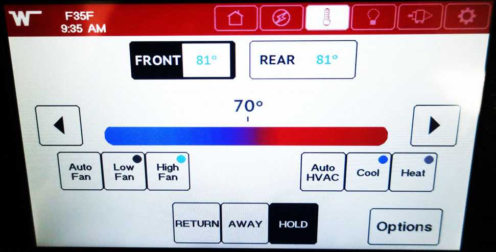
Climate Screen
-Typical View
CONNECTED COACH LIGHTING SCREEN
The Lighting Screen is indicated by the light bulb shaped button located on the selector row at the top. There are 6 primary zones of lights. These are selected using the overhead view picture of the motorhome shown on the screen. Selecting a zone will place a blue box around the area in which the lights are located. By selecting a zone the lights available in that zone will be located at the top of the screen. There is also an exterior lights button, and light master button. The up and down arrows indicate that the light can be dimmed if desired.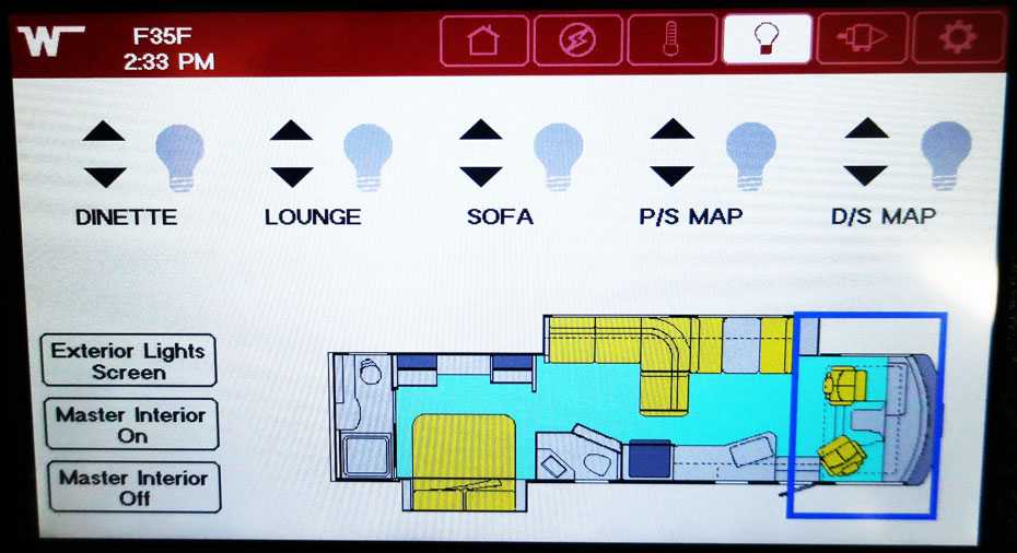
Selecting the front zone controls the driver’s and passenger’s side map lights, as well as the sofa, lounge, and dinette lights.
Typical View
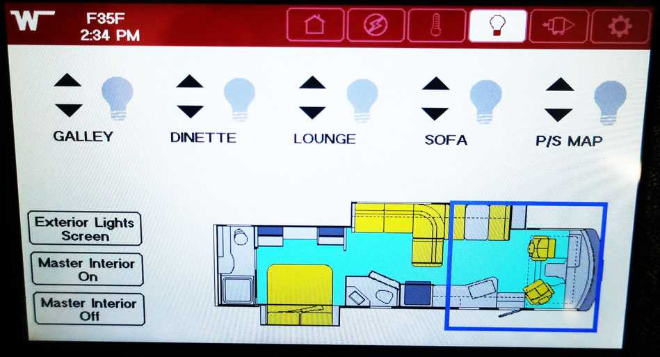
Selecting this zone controls the passenger’s side map lights, sofa, lounge, dinette, and galley lights.
-Typical View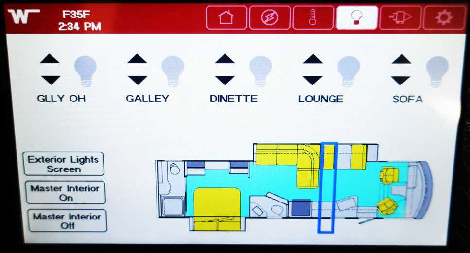
Selecting this zone controls the sofa, lounge, dinette, galley, and galley overhead lights.
-Typical View
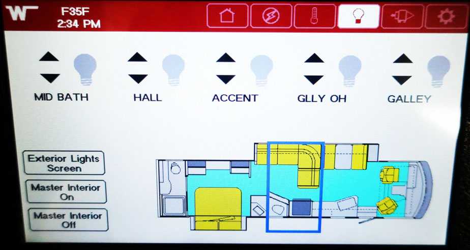
Selecting this zone controls the galley, galley overhead, accent, hall, middle bath lights.
-Typical View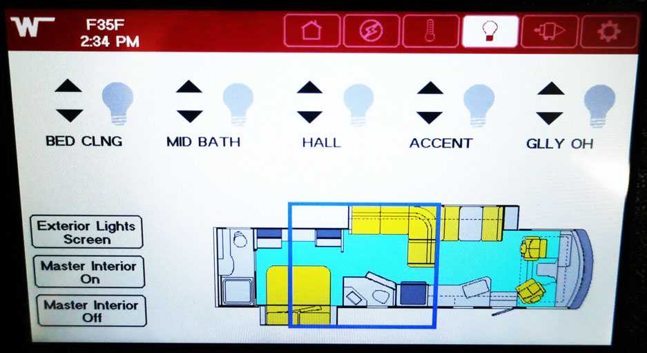
Selecting this zone controls the galley overhead, accent, hall, middle bath, and bed ceiling lights.
-Typical View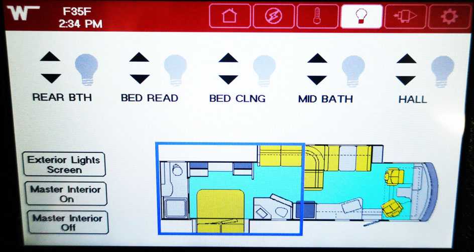
Selecting this zone controls the hall, middle math, bed ceiling, bed reading, and rear bath light.
-Typical View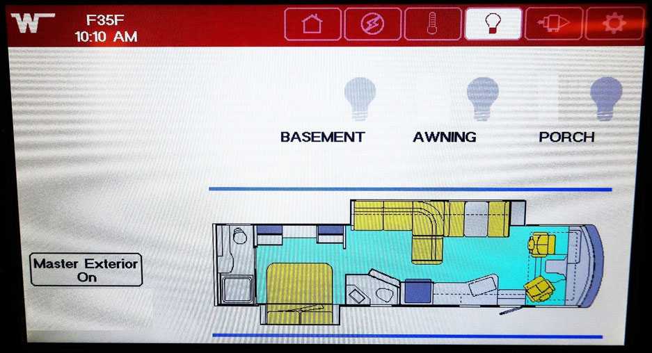
Pressing the Exterior Lights Screen button will reveal the buttons that control the awning, basement, and porch lights.
-Typical View
CONNECTED COACH SLIDEOUT, AWNING AND LEVELING SCREEN
This Screen is indicated by the coach icon located on the selector row at the top. Pressing this button takes you to a menu that accesses the Awning, Slide-out, Jacks, and Bed lift controls. Read the caution instructions carefully on the menus before selecting the corresponding controls.
Awning Controls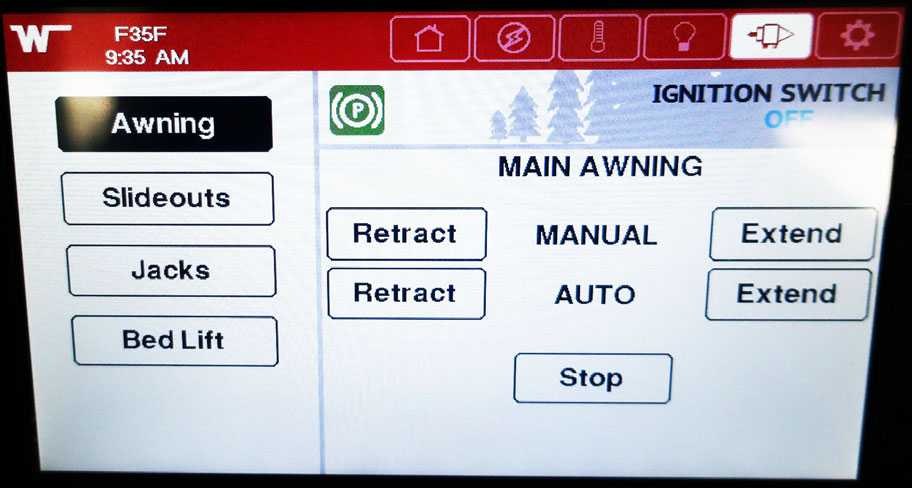
Awning Controls
After reading the warning message, click on the accept button to access the awning controls. Refer to the awning section in the miscellaneous chapter in this manual for operating instructions and safety precautions.
-Typical View
Slide-out Controls
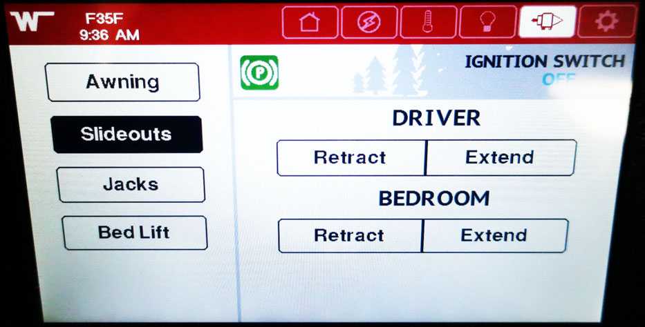
Slide-out Controls
After reading the warning message, click on the accept button to access the slide-out controls. Refer to the slide-out section in the slide-outs and leveling chapter in this manual for operating instructions and safety precautions.
-Typical View
Leveling Controls
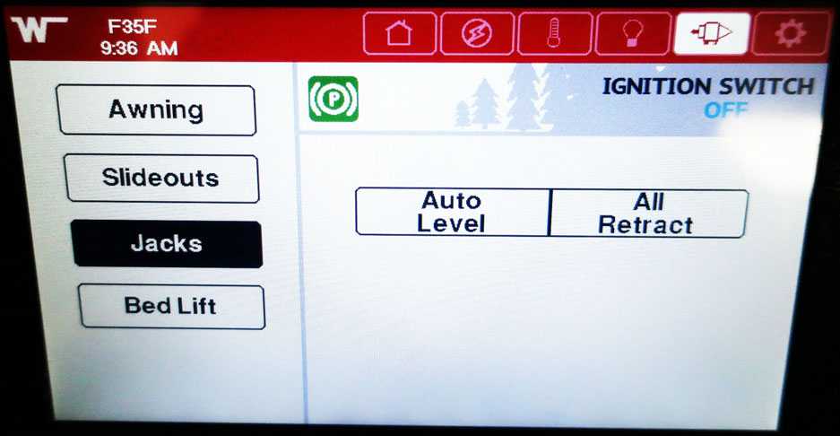
Leveling Controls
After reading the warning message, click on the accept button to access the leveling controls. Refer to the leveling section in the slide-outs and leveling chapter in this manual for operating instructions and safety precautions.
-Typical View
Bed-lift Controls
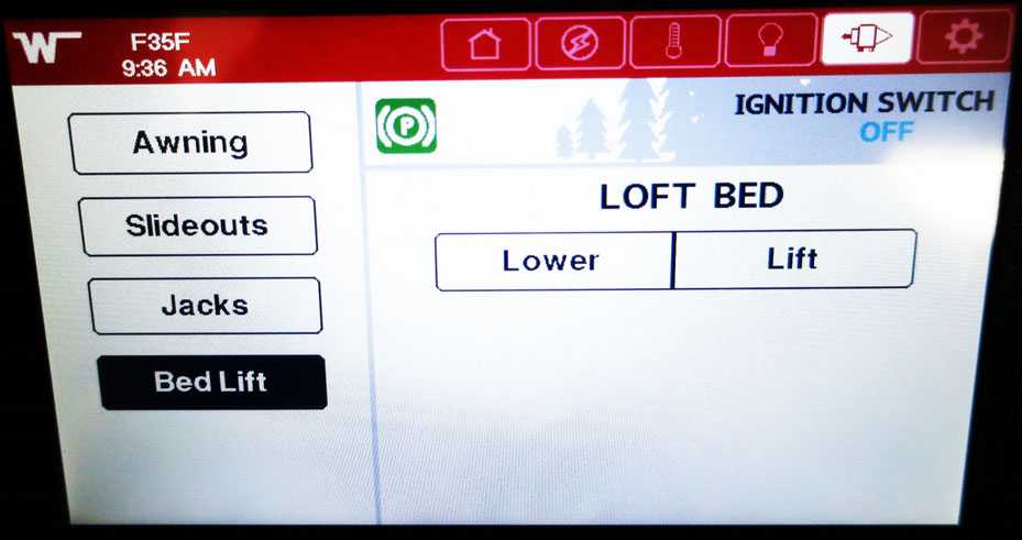
Bed-lift Controls
After reading the warning message, click on the accept button to access the bed-lift controls. Refer to the power loft bed section in the furniture and soft goods chapter in this manual for operating instructions and safety precautions.
-Typical View
CONNECTED COACH SETTINGS SCREEN
The settings screen is indicated by the gear icon button located on the selector row at the top.
Settings Screen 1
This screen has controls for the alarm settings, alarm diagnostics, auto generator start options, awning settings, chassis settings, and climate screen settings.
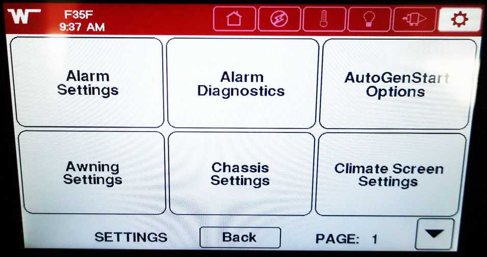
Settings Screen 1
-Typical View
Settings Screen 2
This screen has controls for customizing the monitor, KIB settings, light settings, monitor settings, monitor diagnostics, and network diagnostics.

Settings Screen 2
-Typical View
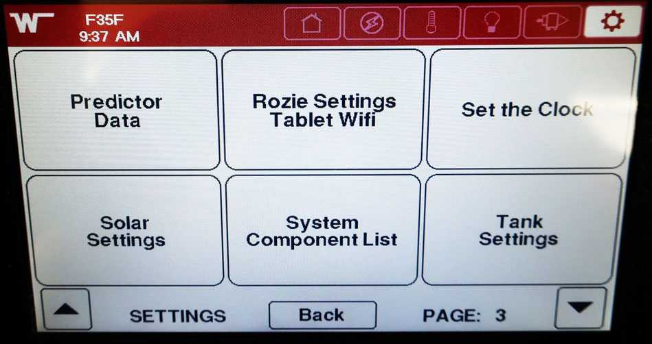
Settings Screen 3
This screen has controls for predictor data, Rosie settings in the tablet WIFI, set the clock, solar settings, system component list, and tank settings.
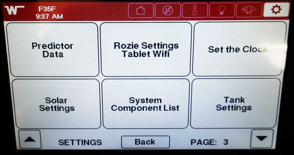 Settings Screen 3
-Typical View
Settings Screen 4
This screen has controls for view logo, view clock, test touchscreen, screen brightness, and reset defaults.
Settings Screen 4
-Typical View
Settings Screen 5
This screen has controls save settings, restore settings, and reboot.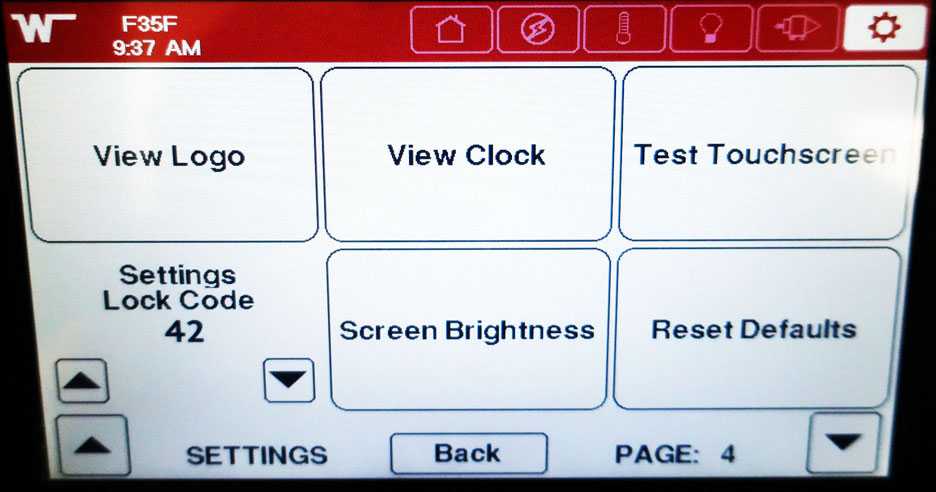
Settings Screen 5
-Typical View
CONNECTED COACH ALERTS WITH DESCRIPTIONS
The following chart explains the alert with the trigger condition. This is a general list of potential Alerts. Some Alerts may not be applicable to all units based on factory-installed equipment and features.
| FRESH TANK LOW | Triggers when fresh tank drops bellow 20% |
| BLACK TANK HIGH | Triggers when black tank goes over 80% |
| GRAY TANK HIGH | Triggers when gray tank goes over 80% |
| LPG TANK LOW | Triggers when LPG tank drops bellow 20% |
| FRESH2 TANK LOW | Triggers when fresh tank #2 drops bellow 20% |
| BLACK2 TANK HIGH | Triggers when black tank #2 goes over 80% |
| GRAY2 TANK HIGH | Triggers when grey tank #2 goes over 80% |
| HOLDING TANK FREEZING | Triggers when a holding tank reaches 0°C(32F) |
| STORAGE BAY FREEZING | Triggers when Storage Bay reaches 0°C(32F) |
| HOLDING TANK NEAR FREEZING | Triggers when a holding tank reaches 5.5°C (42F) |
| STORAGE BAY NEAR FREEZING | Triggers when Storage Bay reaches 5.5°C (42F) |
| INSIDE TEMP LOW | Triggers when interior temp reaches 5.5°C (42F) |
| INSIDE TEMP HIGH | Triggers when interior temp reaches 26.7°C (80F) |
| HOUSE BATTERY VOLTAGE LOW | Triggers when house battery drops to 11.7V |
| HOUSE BATTERY VOLTAGE VERY LOW | Triggers when house battery drops to 10V |
| HOUSE BATTERY SOC% LOW | Triggers when house battery state of charge drops to 20% |
| HOUSE BATTERY |SOC% VERY LOW | Triggers when house battery state of charge drops to 5% |
| HOUSE BATTERY VOLTAGE HIGH | Triggers when house battery reaches 16.5V |
| CHASSIS BATTERY VOLTAGE LOW | Triggers when Chassis battery drops to 11.7V |
| CHASSIS BATTERY VOLTAGE VERY LOW | Triggers when Chassis battery drops to 10V |
| CHASSIS BATTERY VOLTAGE HIGH | Triggers when Chassis battery reaches 15V |
| SHORELINE CONNECTION | Triggers if you are connected to shore power and you turn
the ignition on. (This is to warn you that you should unplug from shore power before moving the coach.) |
| LOW FUEL | Triggers if fuel drops below 20% |
| REFRIGERATOR TEMP HIGH | Triggers if fridge temp reaches 4.4°C (40F) |
| FREEZER TEMP HIGH | Triggers if fridge temp reaches 0°C (32F) |
| OBDII PORT DISCONNECTED | Triggers if motion is detected in the coach, but the speedometer is reporting zero. (This means we can no longer talk to the chassis.) |
| CHASSIS ERROR CODES | Triggers if the chassis connection reports an error. (This is
effectively your check engine light coming on.) |
| BATTERY DISCONNECTED | Triggers if the Charger is on, but the battery voltage is still low. |
WINNEBAGO CONTROL APP
For added convenience an available
“Winnebago Control” app can be downloaded to your personal device(s) for remote control and monitoring of your motorhome’s functions and systems.
NOTE: Keep in mind that each motorhome is unique in its specific features, equipment, systems and floor plan design, and each app is programmed for that specific model’s configuration. Your motorhome’s configuration may vary somewhat from the illustrations shown here, but the basic navigation and user experience will be similar.
- Make sure you are first connected to the onboard Wingard Connect Wi-fi System. Reference the Entertainment section for Wi-Fi connection instructions.
- The Winnebago Control app can be downloaded from the Apple Store for all Apple devices of IOS 13.0 version and higher.
- The Winnebago Control app can be downloaded from the Google Play Store for Android devices version 4.2 or higher.
Near-Field App Use
All functionality present on the app is available in close-proximity or “near-field” of the motorhome. This is achieved through communication of the onboard WiFi system to the connected Coach system.
NOTE: The onboard WiFi system needs to be powered up and operating for near-field operation of the app. You will be able to control these typical mechanical “in motion” functions with the app in “near-field” mode if they are on your motorhome:
- Leveling jacks
- Slide rooms
- Patio awning
- Powered cab bunkbed
NOTE: As with the touchscreen, you will need to check and verify that there are no obstructions or pinch hazards present that could interfere with the operation of these mechanical features by pressing the “Accept” button before initiating operation. Please see the “Slide out” chapter in this manual for further operation.
WARNING
Your motorhome may have more than one slideout room. Understand which switch operates which slideout room prior to operation. Make sure all slideout rooms are clear of people who could be harmed or obstacles that could cause damage prior to operating any slideout rooms. Failure to observe can result in death or serious injury.
Downloading and Setting up the Winnebago Control App
Download the Winnebago Control app on your smartphone.
-Typical View
Winnebago Control App Functions
The Connected Coach software that resides in your motorhome was programmed during the manufacturing process so that the app will be auto-configured specifically to the floor plan, features and equipment of your motorhome when downloaded. The app will typically mirror many of the functions of the main touchscreen monitor, but in a space-consolidated format.
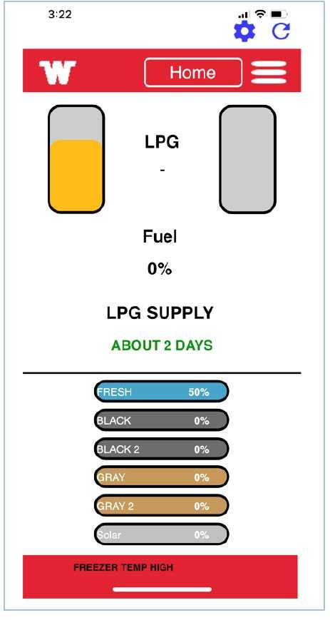
Main Menu Bar Access
-Typical View
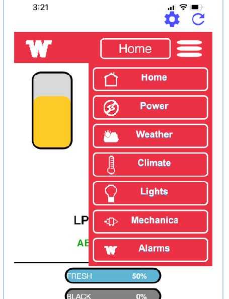
Main Menu Bar (toggle to access available menu functions).
-Typical View
Note: The on-board WiFi system needs to be powered up and operating for operation of the app. Please see the “Onboard WI-FI System” Segment in the Entertainment section of this manual for further instructions.
You will be able to control these typical mechanical “in-motion” functions with the app if they are available on your motorhome.
- Leveling Jacks
- Slide Rooms
- Patio Awning
- Powered Cab Bunk Bed
Note: As is with the Touchscreen, you will need to acknowledge that you have checked and verified that there are no obstructions or pinch hazards present that could interfere with the operation of these mechanical features by pressing the “Accept” button before initiating operation.
Winnebago Control App “Far-field Use Registration”
Your Winnebago Control app can also connect to your coach remotely to monitor and control certain functions.
- Remote or “far-field” app control is limited to non-mechanical functionality such as lighting, tank level check, HVAC system operation, etc. Mechanical “in-motion” functions, such as Leveling Jacks, Slide room and Patio Awning operations, etc. are not available for far-field app control or operation.
- Remote or “far-field” app control is limited to non-mechanical functionality such as lighting, tank level check, HVAC system operation, etc. Mechanical “in-motion” functions, such as Leveling Jacks, Slide room and Patio Awning operations, etc. are not available for far-field app control or operation. strength, it will automatically switch back to near-field mode operation indicated by the “Local” icon (see below).
- Follow the instructions below to register your app for “far-field” usage.
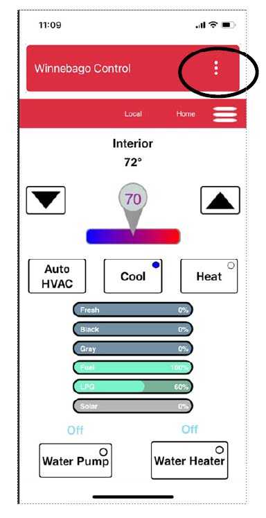
Select the 3 dots at the top.
– Typical View
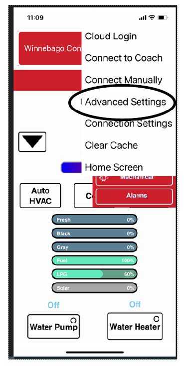
Select “Advanced Settings”
– Typical View
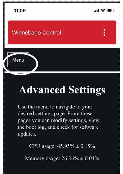
- Select the “Menu” button
– Typical View 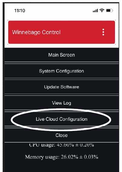
- Select “Live Cloud Configuration”
– Typical View 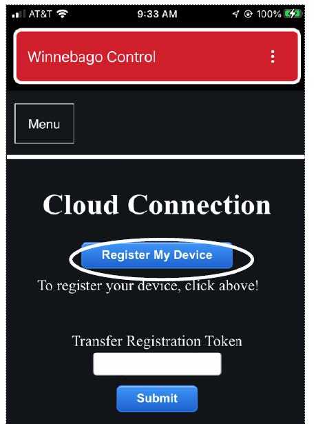
- Select “Register My Device”
– Typical View 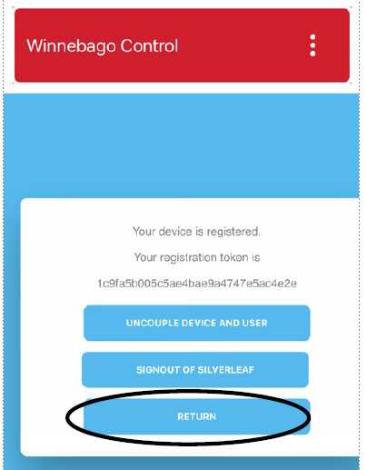
- Select “Return” to go to the login page.
– Typical View 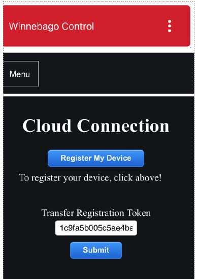
- Select “Submit” after Registration Token is assigned.
-Typical View 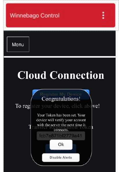
- Select “Ok” command when prompted.
– Typical View 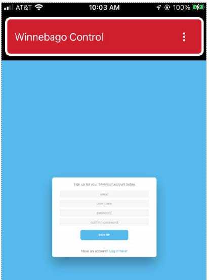
- Fill in the fields as requested to be able to sign up for an account.
-Typical View 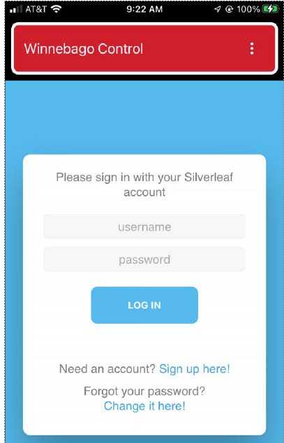
- Log in with username and password at the prompt or sign up if this is your first
account.
-Typical View 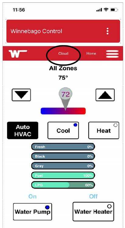
- When the “Cloud” indicator is displayed at the top you are using the app in the “Far-
field” operating mode.
-Typical View 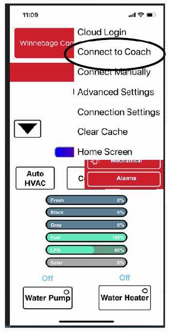
- To manually return to the “Near-field
mode”, select “Connect to Coach” from the pull down menu.
-Typical View 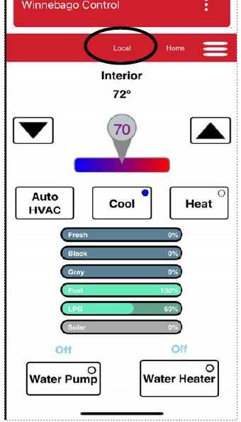
- “Near-field” mode is indicated by the word “Local” at the top.
-Typical View -
Reference Links
View Full User Guide: Winnebago Adventurer 2023 User Manual
Download link: https://www.winnebago.com/owners/owner-resources/manuals-and-diagrams/operator-manuals
