
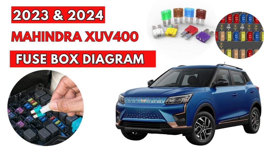
Mahindra XUV400 (2023 & 2024) Fuse Box Diagrams & Location
The Mahindra XUV400 is equipped with strategically placed fuse boxes that protect its electrical systems and components. This blog covers the Mahindra XUV400 (2023 & 2024) fuse box locations and diagrams, helping you identify fuse positions and understand their functions when checking electrical issues.
Fuse Box Location
Passenger Compartment Fuse Box
This fuse box is located below the Instrument panel on the driver side. To access the fuse box, pull out the top panel.

Engine Compartment Fuse Box
Motor compartment fuse box is located adjacent to vehicle battery. To open the fuse box cover, press the lock and push the cover back and lift it.

Fuse Box Diagrams
Passenger Compartment Fuse Box

| № | Amps | CIRCUIT |
|---|---|---|
| FS1 | 25A | MBFM-1 |
| FS2 | 15A | Audio |
| FS3 | 10A | Cluster, HVAC, S/Visor Lamp, Center Fascia Sw |
| FS4 | 5A | ESCL |
| FS5 | 5A | Room Lamp |
| FS6 | 10A | Reverse Lamp |
| FS7 | 10A | Cluster EPS, PKE, IMMO, Auto Light |
| FS8 | 10A | Can Gateway |
| FS9 | 10A | MBFM |
| FS10 | 5A | PKE (For PKE Variant) |
| FS11 | – | – |
| FS12 | – | – |
| FS13 | – | – |
| FS14 | 30A | P/Outlet |
| FS15 | 10A | SBW/TGS |
| FS16 | 10A | Audio |
| FS17 | 10A | HLLD |
| FS18 | 10A | Can Gateway |
| FS19 | 10A | Airbag, PAB Off Sw |
| FS20 | 10A | Audio, Rear Camera, Telematics |
| FS21 | 30A | MBFM-3 |
| FS22 | 30A | MBFM-2 |
| FS23 | 30A | MBFM-5 |
| FS24 | 30A | MBFM-4 |
| FS25 | 15A | CCM |
| FS26 | 10A | Spare |
| FS27 | 5A | PKE, Sunroof SW |
| FS28 | 20A | Sunroof Motor |
| FS29 | 15A | PKE (For PKE Variant) |
| FS30 | 10A | Diagnostic, IMMO, Telematics |
| FS31 | – | – |
| FS32 | 10A | Spare |
| FS33 | 20A | Spare |
| FS34 | 10A | Spare |
| FS35 | 10A | Outside Mirror |
| FS36 | 10A | Start/T50 |
| FS37 | 10A | ABS |
| FS38 | 10 | VCU |
| FS39 | 10A | Spare |
| FS40 | 40A | Blower RLY Coil |
| FS41 | – | – |
| FS42 | 25A | Power Window Left |
| FS43 | 15A | Spare |
| FS44 | 25A | Power Window Right |
Engine Compartment Fuse Box
Main Fuse Box
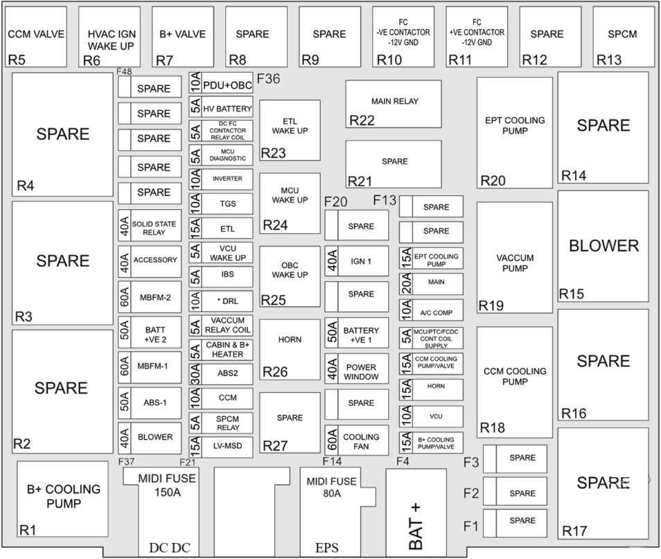
| № | Amps | CIRCUIT |
|---|---|---|
| F1 | – | Spare |
| F2 | – | Spare |
| F3 | – | Spare |
| F4 | 15A | B+ Cooling Pump/Valve |
| F5 | 10A | VCU |
| F6 | 15A | Horn |
| F7 | 15A | CCM Cooling Pump/Valve |
| F8 | 5A | MCU/PTC/FCDC Coil Supply |
| F9 | 10A | A/C Com |
| F10 | 20A | Main |
| F11 | 15A | EPT Cooling Pump |
| F12 | – | Spare |
| F13 | – | Spare |
| F14 | 60A | Cooling Fan |
| F15 | – | Spare |
| F16 | 40A | Power Window |
| F17 | 50A | Battery +VE I |
| F18 | – | Spare |
| F19 | 40A | IGN I |
| F20 | – | Spare |
| F21 | 15A | LV-MSD |
| F22 | 5A | SPCM Relay |
| F23 | 10A | CCM |
| F24 | 30A | ABS 2 |
| F25 | 5A | Cabin & B+ Heater |
| F26 | 5A | Vaccum Pump Relay Coil |
| F27 | 10A | DRL |
| F28 | 5A | IBS |
| F29 | 5A | VCU Wakeup |
| F30 | 15A | ETL |
| F31 | 10A | TGS |
| F32 | 10A | Inverter |
| F33 | 5A | MCU Diagnostic |
| F34 | 5A | DC FC Contactor Relay Coil |
| F35 | 5A | HV Battery |
| F36 | 10A | PDU+OBC |
| F37 | 40A | Blower |
| F38 | 50A | ABS-I |
| F39 | 60A | MBFM-1 |
| F40 | 50A | Batt +VE 2 |
| F41 | 60A | MBFM-2 |
| F42 | 40A | Accessory |
| F43 | 40A | Solid State Relay |
| F44 | – | Spare |
| F45 | – | Spare |
| F46 | – | Spare |
| F47 | – | Spare |
| F48 | – | Spare |
| 150A | DC DC | |
| 80A | EPS | |
| – | BAT + | |
| Relays | ||
| R1 | B+ Cooling Pump | |
| R2 | Spare | |
| R3 | Spare | |
| R4 | Spare | |
| R5 | CCM Valve | |
| R6 | HVAC IGN Wake Up | |
| R7 | B+ Valve | |
| R8 | Spare | |
| R9 | Spare | |
| R10 | FC -VE Contactor -12v Gnd | |
| R11 | FC +VE Contactor -12v Gnd | |
| R12 | Spare | |
| R13 | SPCM | |
| R14 | Spare | |
| R15 | Blower | |
| R16 | Spare | |
| R17 | Spare | |
| R18 | CCM Cooling Pump | |
| R19 | Vaccum Pump | |
| R20 | EPT Cooling Pump | |
| R21 | Spare | |
| R22 | Main Relay | |
| R23 | ETL Wakeup | |
| R24 | MCU Wakeup | |
| R25 | OBC Wakeup | |
| R26 | Horn | |
| R27 | Spare |
Battery Mounted Fuse Box
| Amps | Circuit |
|---|---|
| 150A | DC DC |
| 100A | EC FB |
Related Posts: