
BAIC BJ80 2024 Fuse Box Diagrams & Location
The BAIC BJ80 2024 uses fuse boxes to protect important electrical circuits and components. Knowing the correct fuse locations and assignments makes troubleshooting electrical problems easier. This guide covers fuse box locations, diagrams, fuse ratings, and protected components for the BAIC BJ80.
Fuse Box Location
Passenger Compartment Fuse Box
Remove the inner fuse box cover in the direction of the arrow.
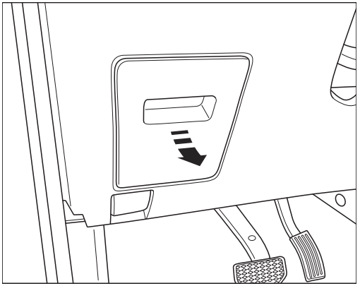
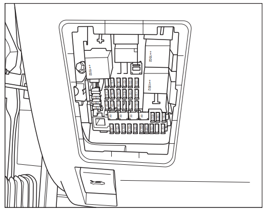
The interior fuse box is located on the left side of the lower steering column of the dashboard and behind the knee protection cover plate, and the knee pad should be removed for easy viewing during inspection or maintenance.
Engine Compartment Fuse Box
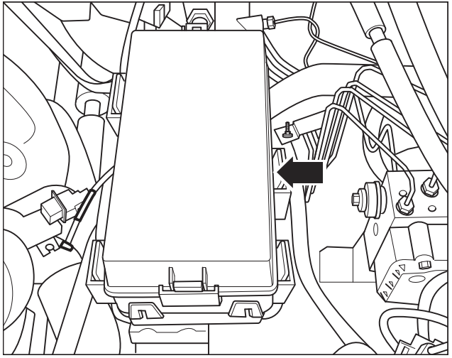
The engine compartment power distribution centre is located in front of the battery.
Fuse Box Diagrams
Passenger Compartment Fuse Box
Equipped with gasoline engine models
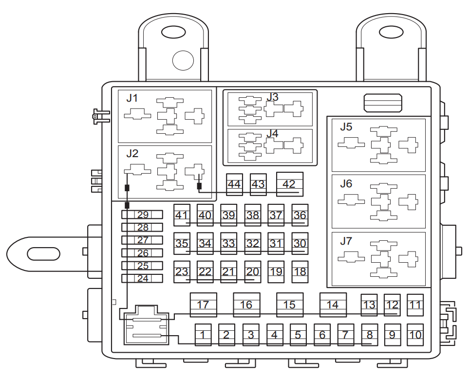
Gasoline engine (3.0T models)
| Position | Specification | Function |
|---|---|---|
| 1 | 30A | B+ |
| 2 | 30A | 220V |
| 3 | 10A | Left front door module |
| 4 | 10A | BCM Lighting |
| 5 | 20A | BCM door lock |
| 6 | 10A | BCM Lighting |
| 7 | 20A | Four-wheel drive controller |
| 8 | 10A | Left rear door module |
| 9 | 10A | Interior light |
| 10 | 5A | AV / Rear-row screen / Amplifier |
| 11 | 15A | 12V |
| 12 | 30A | Sunroof / Recorder |
| 13 | 7.5A | PEPS |
| 14 | 30A | Front passenger / Right rear seat adjustment |
| 15 | 30A | Right glass motor |
| 16 | 30A | Driver / Left rear seat adjustment |
| 17 | 30A | Left glass motor |
| 18 | 25A | Cigarette lighter ACC |
| 19 | 5A | Gateway IG |
| 20 | 10A | Rear display screen |
| 21 | 5A | Seat module |
| 22 | 5A | Air conditioner |
| 23 | 30A | Pedal lever module |
| 24 | 5A | PEPS |
| 25 | 30A | Driver / Left rear seat heating |
| 26 | 30A | Front passenger / Right rear seat heating |
| 27 | 15A | BCM |
| 28 | 30A | Power amplifier |
| 29 | 15A | Front fog light |
| 30 | 5A | ESP / Shift mechanism |
| 31 | 15A | Steering wheel heating |
| 32 | 7.5A | Body / Roof |
| 33 | 10A | Instrument / Central Control / TPMS |
| 34 | 10A | Airbag |
| 35 | 5A | IG+ |
| 36 | 10A | Right rear door module |
| 37 | 10A | Right front door module |
| 38 | 5A | Gateway |
| 39 | 15A | Video & audio |
| 40 | 5A | Instrument |
| 41 | 5A | Air Conditioning / Central Control / Brake Switch |
| 42 | 30A | Rear defrost |
| 43 | — | Reserved |
| 44 | — | Reserved |
| J1 | — | Reserved |
| J2 | Small relay | Defroster relay |
| J3 | Small relay | Left front fog light relay |
| J4 | Small relay | Right front fog light relay |
| J5 | Small relay | ACC relay |
| J6 | Small relay | IG relay |
| J7 | — | Reserved |
Gasoline engine (2.3T models)
| Position | Specification | Function |
|---|---|---|
| 1 | 30A | B+ |
| 2 | 30A | 220V Power |
| 3 | 10A | Left front door module |
| 4 | 10A | BCM Lighting power supply |
| 5 | 20A | BCM door lock power supply |
| 6 | 10A | BCM Lighting power supply |
| 7 | 20A | 4WD controller power supply |
| 8 | 10A | Left rear door module power supply |
| 9 | 10A | Interior lamp power |
| 10 | 5A | AV ACC power |
| 11 | 15A | Passenger seat adjustment power supply |
| 12 | 30A | Sunroof power supply |
| 13 | 7.5A | PEPS power supply |
| 14 | 30A | Passenger seat adjustment power supply |
| 15 | 30A | Left window regulator motor |
| 16 | 30A | Driver’s seat adjustment power |
| 17 | 30A | Left glass regulator motor |
| 18 | 15A | Cigarette lighter ACC power supply |
| 19 | 5A | Gateway IG1 power supply |
| 20 | 10A | Rear display screen power supply |
| 21 | 5A | Seat module |
| 22 | 5A | A/C IGN2 power supply |
| 23 | 20A | Pedal module power supply |
| 24 | 5A | PEPS power supply |
| 25 | 30A | Driver/left rear seat heating power supply |
| 26 | 30A | Front passenger/left rear seat heating power supply |
| 27 | 15A | BCM power supply |
| 28 | 30A | Power amplifier power supply |
| 29 | 15A | Front fog light power supply |
| 30 | 5A | ESP Shift mechanism |
| 31 | 15A | TCU IGN1 power supply |
| 32 | 7.5A | Body & Roof |
| 33 | 10A | Instrument, central control, tire pressure monitoring module & 4WD switch |
| 34 | 10A | Airbag module IGN1 power supply |
| 35 | 5A | IGN1 power supply |
| 36 | 10A | Right rear door module power supply |
| 37 | 10A | Right front door module power supply |
| 38 | 5A | Gateway power |
| 39 | 15A | AV & OBD interface power supply |
| 40 | 5A | Instrument power supply |
| 41 | 5A | A/C & central control power supply |
| 42 | 30A | Rear windshield defrost power supply |
| 43 | — | Reserved |
| 44 | — | Reserved |
| J1 | — | Reserved |
| J2 | Small relay | Defroster relay |
| J3 | Small relay | IGN2 relay |
| J4 | Small relay | Front fog light relay |
| J5 | Small relay | ACC relay |
| J6 | Small relay | IGN1 relay |
| J7 | — | Reserved |
Engine Compartment Fuse Box
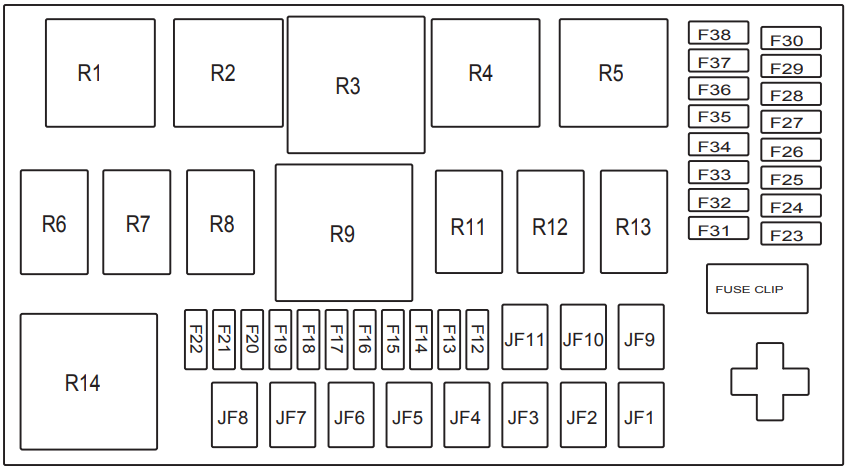
(3.0T model)
| Position | Specification | Function |
|---|---|---|
| R1 | Small Relay | Main Relay |
| R2 | Small Relay | Start Relay |
| R3 | — | Reserved |
| R4 | Small Relay | Low-Beam Relay |
| R5 | Small Relay | Horn Relay |
| R6 | Small Relay | Compressor Relay |
| R7 | Small Relay | Headlight Washer Relay |
| R8 | Small Relay | Water Pump Relay |
| R9 | — | Reserved |
| R11 | Small Relay | Low-Speed Wiper Relay |
| R12 | Small Relay | High-Speed Wiper Relay |
| R13 | Small Relay | Fuel Pump Relay |
| R14 | — | Reserved |
| JF1 | 60A IEC | — |
| JF2 | 40A ESP | — |
| JF3 | — | Reserved |
| JF4 | — | Reserved |
| JF5 | 30A IG1 | — |
| JF6 | 40A | Air Blower |
| JF7 | 30A | Starter |
| JF8 | 30A | Main Relay |
| JF9 | 30A | Front Wiper |
| JF10 | 30A | Headlamp Washing |
| JF11 | 60A IEC | — |
| F12 | 7.5A | EMS |
| F13 | 15A | Horn |
| F14 | 30A | Low-Beam Light |
| F15 | 10A | Water Pump |
| F16 | 10A | Compressor |
| F17 | — | Reserved |
| F18 | — | Reserved |
| F19 | 20A | Oil Pump |
| F20 | 25A ESP | — |
| F21 | 5A | Headlight Adjustment |
| F22 | 10A | TCU |
| F23 | — | Reserved |
| F24 | — | Reserved |
| F25 | 15A | Engine System Sensor |
| F26 | 15A | Injectors & Ignition Coils |
| F27 | 5A | Start Feedback |
| F28 | 10A | Engine Controller |
| F29 | — | Reserved |
| F30 | — | Reserved |
| F31 | — | Reserved |
| F32 | — | Reserved |
| F33 | — | Reserved |
| F34 | — | Reserved |
| F35 | — | Reserved |
| F36 | — | Reserved |
| F37 | 20A | Reserve |
| F38 | 15A | Reserve |
(2.3T model)
| Position | Specification | Function |
|---|---|---|
| R1 | Small Relay | Main Relay |
| R2 | Small Relay | Starter Relay |
| R3 | Small Relay | Fan High-Speed Relay |
| R4 | Small Relay | Low-Beam Relay |
| R5 | Small Relay | Horn Relay |
| R6 | Small Relay | Compressor Relay |
| R7 | Small Relay | Headlight Washer Relay |
| R8 | — | Reserved |
| R9 | Small Relay | Fan High-Speed Relay |
| R11 | Small Relay | Low-Speed Wiper Relay |
| R12 | Small Relay | High-Speed Wiper Relay |
| R13 | Small Relay | Fuel Pump Relay |
| R14 | Small Relay | Fan Low-Speed Relay |
| JF1 | 60A IEC | Power Supply |
| JF2 | 40A ESP | Power Supply |
| JF3 | 60A | Low-Speed Fan |
| JF4 | 40A | High-Speed Fan 1 |
| JF5 | 30A IG1/ACC | Power Supply |
| JF6 | 40A | Air Blower |
| JF7 | 30A IG2/Starter | Power Supply |
| JF8 | 40A | Main Relay |
| JF9 | 30A | Front Wiper |
| JF10 | 30A | Headlight Cleaning |
| JF11 | 40A | High-Speed Fan 2 |
| F12 | 10A | EMS Power Supply |
| F13 | 15A | Horn |
| F14 | 30A | Low-Beam Light |
| F15 | — | Reserved |
| F16 | 10A | Compressor Clutch |
| F17 | — | Reserved |
| F18 | — | Reserved |
| F19 | 20A | Oil Pump |
| F20 | 25A ESP | — |
| F21 | 5A | Headlight Level Adjustment |
| F22 | 5A | TCU Power Supply |
| F23 | — | Reserved |
| F24 | — | Reserved |
| F25 | 15A | Fuel Injector Sensor |
| F26 | 15A | Ignition Coil |
| F27 | 5A | Start Feedback |
| F28 | — | Reserved |
| F29 | — | Reserved |
| F30 | — | Reserved |
| F31 | — | Reserved |
| F32 | — | Reserved |
| F33 | — | Reserved |
| F34 | — | Reserved |
| F35 | — | Reserved |
| F36 | — | Reserved |
| F37 | 20A | Reserve |
| F38 | 15A | Reserve |
Fuse box layout on battery
Equipped with gasoline engine models
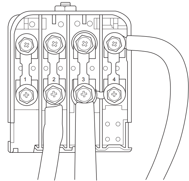
Gasoline engine (2.3T models)
| Position | Specification | Function |
|---|---|---|
| 1 | 125A | Reserved |
| 2 | 175A | Engine Compartment Fuse Box Power Supply |
| 3 | 175A | Alternator |
| 4 | 80A | Dashboard Fuse Box |
Gasoline engine (3.0T models)
| Position | Specification | Function |
|---|---|---|
| 1 | 60A | Right Fan |
| 2 | 175A | Engine Compartment Fuse Box Power Supply |
| 3 | 175A | Alternator |
| 4 | 60A | Left Fan |
Related Posts: