


2024 Cadillac XT4 Fuses and Fuse Box Diagrams User Guide
Clear fuse box diagrams show 2024 Cadillac XT4 fuse locations, amperage ratings, and circuit assignments. Learn to locate, replace, and fix blown fuses for DIY electrical maintenance and vehicle performance.
2023 Cadillac XT4 Specs, Price, Features, Mileage and Torque (Review)
Video: 2024 Cadillac XT4 Fuses
Electrical System
Electrical System Overload
The vehicle has fuses and circuit breakers to protect against an electrical system overload. When the current electrical load is too heavy, the circuit breaker opens and closes, protecting the circuit until the current load returns to normal or the problem is fixed. This greatly reduces the chance of circuit overload and fire caused by electrical problems.
Fuses and circuit breakers protect power devices in the vehicle.
If there is a problem on the road and a fuse needs to be replaced, the same amperage fuse can be borrowed. Choose some feature of the vehicle that is not needed to use and replace it as soon as possible.
To check a fuse, look at the band inside the fuse. If the band is broken or melted, replace the fuse. Be sure to replace a bad fuse with a fuse of identical size and rating.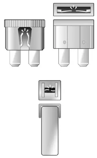
Replacing a Blown Fuse
- Turn off the vehicle.
- Locate the fuse puller in the engine compartment fuse block.

- Use the fuse puller to remove the fuse from the top or side, as shown above.
- If the fuse must be replaced immediately, borrow a replacement fuse with the same amperage from the fuse block. Choose a vehicle feature that is not needed to safely operate the vehicle. Repeat Steps 2-3.
- Insert the replacement fuse into the empty slot of the blown fuse.
At the next opportunity, see your dealer to replace the blown fuse.
Headlamp Wiring
An electrical overload may cause the lamps to go on and off, or in some cases to remain off. Have the headlamp wiring checked right away if the lamps go on and off or remain off?
Windshield Wipers
If the wiper motor overheats due to heavy snow or ice, the windshield wipers will stop. The wiper function is available immediately after the wiper switch is set to off, and back to on. To protect the wiper motor from overheating, the wipers may slow down when the windshield is dry for a long period. If a period of dry operation, or little moisture, exceeds 10 minutes, the wipers may switch to intermittent operation, and remain there. When moisture is again detected on the windshield, wiper operation will return to the operator-selected speed.
Although the circuit is protected from electrical overload, overload due to heavy snow or ice may cause wiper linkage damage. Always clear ice and heavy snow from the windshield before using the windshield wipers.
If the overload is caused by an electrical problem and not snow or ice, be sure to get it fixed.
Fuses and Circuit Breakers
The wiring circuits in the vehicle are protected from short circuits by a combination of fuses and circuit breakers. This greatly reduces the chance of damage caused by electrical problems.
Danger
Fuses and circuit breakers are marked with their ampere rating. Do not exceed the specified amperage rating when replacing fuses and circuit breakers. The use of an oversized fuse or circuit breaker can result in a vehicle fire. You and others could be seriously injured or killed.
Warning
Installation or use of fuses that do not meet GM’s original fuse specifications is dangerous. The fuses could fail, and result in a fire. You or others could be injured or killed, and the vehicle could be damaged.
Engine Compartment Fuse Block
The underhood fuse block is in the engine compartment, on the driver’s side of the vehicle.
Caution
Do not pull the engine compartment fuse block lever, since it is intended only for service purposes. If pulled, vehicle malfunction may occur.
Caution
Spilling liquid on any electrical component of the vehicle may damage it. Always keep the covers on any electrical component.
To remove the fuse block cover, press the clips on the cover and lift it straight up.
The vehicle may not be equipped with all of the fuses, relays, and features shown.
| Fuse | Usage |
| 1 | Spare |
| 2 | Aeroshutter |
| 3 | Spare |
| 4 | Spare |
| 5 | Spare |
| 6 | – |
| 7 | ECM 2 – Engine Control Module 2/ECM 3– Engine Control Module 3 |
| 8 | ECM MAIN– Engine Control Module Main |
| 9 | – |
| 10 | OFF ENG |
| – | |
| 11 | OFF ENG 2/OFF ENG 1 |
| 12 | 0CAC – Charge Air Cooler/ ECM – Engine Control Module |
| 13 | TCM – Transmission Control Module |
| 14 | – |
| 15 | – |
| 16 | – |
| 17 | A/C Control |
| 18 | – |
| 19 | Starter Pinion |
| 20 | MCU – Microprocessor Control Unit |
| 21 | – |
| 22 | – |
| 23 | – |
| 24 | – |
| 25 | Starter Motor |
| 26 | Spare |
| 27 | – |
| 28 | – |
| 29 | – |
| 30 | – |
| 31 | – |
| 32 | Spare |
| 33 | Spare |
| 34 | ELM 5 – Exterior Lighting Module 5 |
| 35 | Power Sounder |
| 36 | ELM 4 – Exterior Lighting Module 4 |
| 37 | ELM 3 – Exterior Lighting Module 3 |
| 38 | MSM_E – Memory Seat Module |
| 39 | BSM – Battery State Module |
| 40 | Front Window Switch |
| – | |
| 41 | RDCM BATT 2 – Rear Drive Control Module Battery 2 |
| – | |
| 42 | Headlamp Right and Headlamp Left |
| 43 | FRT HTD SEAT MDL – Front Heated Seat Module |
| 44 | RFAM & AFL/AHL/RDCM BAT 2 – Radio Frequency Actuator Module and Adaptive Forward Lighting/ Automatic Headlamp Leveling/Rear Drive Control Module Battery 2 |
| 46 | – |
| 47 | – |
| 48 | DC-DC BAT 2 – Direct Current Direct Current Battery 2 |
| 49 | – |
| 50 | MTR WDW LIFTER LT – Motor Window Lifter Left |
| 51 – | |
| 52 | Passenger Power Seat |
| 53 | – |
| 54 | TIM 1 – Trailer Interface Module 1 |
| 55 | TIM 2 – Trailer Interface Module 2 |
| 56 | Trailer Park Lamps |
| 57 | RDCM BATT 1 – Rear Drive Control Module Battery 1 |
| 58 | Driver Power Seat |
| 59 | EBCM – Electronic Brake Control Module |
| 60 | Horn |
| 61 | Rear Defog |
| 62 | Front Wiper |
| 63 | Power Tailgate |
| 64 | MTR WDW LIFTER RT – Motor Window Lifter Right |
| 65 | – |
| 66 | Sunroof |
| 67 | Trailer Run |
| 68 | Spare |
| 69 | Spare |
| 70 | – |
| 71 | – |
| 72 | FTZM – Fuel Tank Zone Module |
| 73 | Handsfree Closure |
| 74 | – |
| 75 | Spare |
| 76 | Spare |
| 77 | Spare |
| 78 | Trailer Stop/Turn Left and Right |
| 79 | TCM (DC to DC) – Transmission Control Module |
| 80 | – |
| 81 | SADS – Semi-Active Dampening Suspension |
| 82 | – |
| 83 | Washer Pump |
Instrument Panel Fuse Block
 The instrument panel fuse block is on the driver’s side of the instrument panel, between the steering wheel and the door. To access the fuses, remove the panel, starting at the top. Once clips are disengaged, the tabs along the bottom of the door can be disengaged from the instrument panel to remove the door. To reinstall the door, place the bottom tabs into the slots, and rotate the door into position, engaging the clips. The vehicle may not be equipped with all of the fuses, relays, and features shown.

| Fuse | Usage |
| F1 | Blower Motor |
| F2 | ELM 1 – Exterior Lighting Module 1 |
| F3 | Column Lock |
| F4 | ELM 2 – Exterior Lighting Module 2 |
| F5 | BCM 2 – Body Control Module 2 |
| F6 | Amplifier |
| F7 | Clock Spring |
| F8 | DLC – Data Link Connector |
| F9 | BCM 1 – Body Control Module 1/SIB – Shifter Interface Board |
| F10 | Headliner/Auxiliary Switch |
| F11 | Display and HVAC |
| F12 | Steering Column Lock |
| F13 | Video Driving Monitoring System (DMS)/Safety 2 |
| F14 | RC MISC 3/ECM – Ride Control Miscellaneous 3/ Electronic Control Module |
| F15 | Rear Wiper |
| F16 | Cargo APO – Cargo Auxiliary Power Outlet |
| F17 | Sensing Diagnostic Module (SDM)/Safety 1 |
| F18 | RC MISC 1/MISC 2 –Ride Control Miscellaneous 1/ Miscellaneous 2 |
| F19 | Exterior Lighting Module (ELM) TR6 |
| F20 | Central Gateway Module(CGM)/Telematics (OnStar) |
| F21 | – |
| F22 | European Trailer |
| F23 | Auxiliary Power Outlet (APO) Cigar |
| F24 | Wireless Charger |
| F25 | USB |
| F26 | ELM 6 – Exterior Lighting Module 6 |
| F27 | VCU AUX JACK – Vehicle Communication Unit Auxiliary Jack |
| F28 | ELM 7– Exterior Lighting Module 7 |
| F29 | – |
| F30 | – |
| F31 | BCM 3 – Body Control Module 3 |
| F32 | HSWM – Heated Steering Wheel Module |
| F33 | – |
| F34 | STEERING CLMN ADJ MDL – Steering Column Adjacent Module |
| F35 | Amplifier |
| F36 | DC/DC BATT 2 |
| F37 | – |
| F38 | – |
| F39 | BCM 4 – Body Control Module 4 |
| F40 | – |
| Relay | Usage |
| CB01 | Auxiliary Power Outlet (APO) Row 2 |
| CB02 | Auxiliary Power Outlet (APO) Row 1 |
Useful Link:
View Full PDF: 2024 Cadillac XT4 Owner’s Manual | Auto User Guide
2024 Cadillac XT4 Displays Control | Complete Guidance
2023 Cadillac XT4 Specs, Price, Features, Mileage and Torque (Review)