
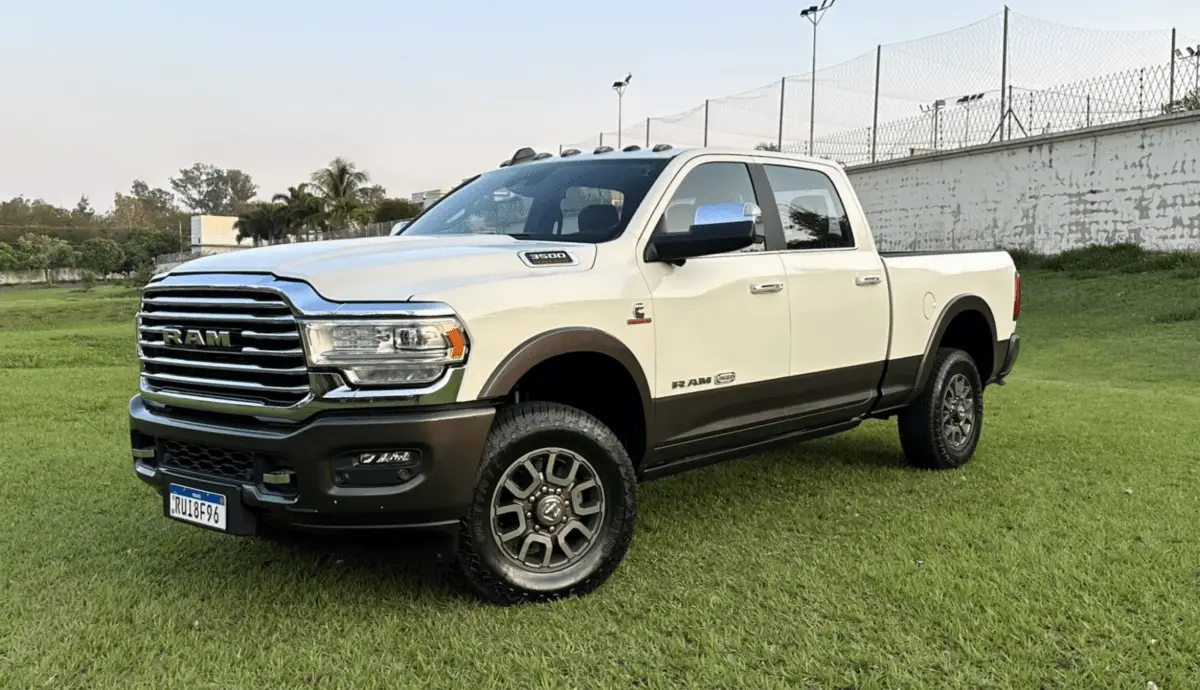

2024 RAM 3500 Fuses and Fuse Box Diagram User Guide
This Guide covers the 2024 RAM 3500 fuses and fuse box diagram, including their locations, functions, and how to replace blown fuses to keep your truck’s electrical systems running well.
2023 RAM PROMASTER Specs, Price, Features, Mileage And Review
Video: 2024 RAM 3500 Fuses and Fuse
FUSES
General Information
WARNING!
- When replacing a blown fuse, always use an appropriate replacement fuse with the same amp rating as the original fuse. Never replace a fuse with another fuse of a higher amp rating. The use of a fuse with a rating other than indicated may result in a dangerous electrical system overload. If a properly rated fuse continues to blow, it indicates a problem in the circuit that must be corrected. Never replace a blown fuse with metal wires or any other material. Do not place a fuse inside a circuit breaker cavity or vice versa. Failure to use proper fuses may result in serious personal injury, fire, and/or property damage.
- Before replacing a fuse, make sure that the ignition is off and that all the other services are switched off and/or disengaged.
- If the replaced fuse blows again, contact an authorized dealer.
- If a general protection fuse for safety systems (air bag system, braking system), power unit systems (engine system, transmission system), or steering system blows, contact an authorized dealer.
CAUTION!
If it is necessary to wash the engine compartment, take care not to directly hit the fuse box and the windshield wiper motors with water.
The fuses protect electrical systems against excessive current.
When a device does not work, you must check the fuse element inside the blade fuse for a break/melt.
Also, please be aware that using power outlets for extended periods with the engine off may result in vehicle battery discharge.
 Blade Fuses
- Fuse Element
- Blade Fuse with a good/functional fuse element
- Blade Fuse with a bad/not functional fuse element (blown fuse)
Power Distribution Center
The Power Distribution Center is located in the engine compartment near the battery. This center contains cartridge fuses, micro fuses, relays, and circuit breakers. A description of each fuse and component may be stamped on the inside cover, otherwise, the cavity number of each fuse is stamped on the inside cover that corresponds to the following chart.
CAUTION!
- When installing the power distribution center cover, it is important to ensure the cover is properly positioned and fully latched. Failure to do so may allow water to get into the power distribution center and possibly result in an electrical system failure.
- If it is necessary to wash the engine compartment, take care not to directly hit the fuse box, and the windshield wiper motor with water.

| Cavity | Cartridge Fuse | Micro Fuse | Description |
|
If Equipped |
|||
| F01 | – | – | Spare |
| F02 | 60 Amp Yellow | – | ABS Pump Mtr |
| F03 | 60 Amp Yellow | – | Rad Fan HI / Lo * |
| F04 | 50 Amp Red | – | 400W Inverter |
| F05 | 50 Amp Red | – | Air Suspension Comp |
| F06 | 40 Amp Green | – | STORM |
| F07 | 40 Amp Green | – | Starter Solenoid |
| F08 | 20 Amp Blue | – | NOX Sensor * |
|
F09 |
30 Amp Pink |
– |
Gas – Brake Vacuum Pump * |
| 40 Amp Green | Diesel – Fuel Heater * | ||
| F10 | 40 Amp Green | – | CBC #2 / Ext Lights |
| F11 | 40 Amp Green | – | Brake SYS MOD ECU & Valves |
| F12 | 40 Amp Green | – | CBC #3 / Pwr Locks |
| F13 | 40 Amp Green | – | HVAC Blwr Mtr |
| F14 | 40 Amp Green | – | CBC #4 / Ext Light |
| F15 | 30 Amp Pink | – | Power Side Step* |
| F16 | 30 Amp Pink | – | Smart – Bar Module * |
| F17 | 30 Amp Pink | – | Winch * |
| F18 | – | – | Spare |
| F19 | 30 Amp Pink | – | Diesel SCR Feed * |
| F20 | 30 Amp Pink | – | Passenger Door Mod |
| F21 | 30 Amp Pink | – | DTCM |
|
F22 |
20 Amp Blue |
– |
Gas – ECM * |
| 25 Amp White | Diesel – PCM * | ||
| F23 | 30 Amp Pink | – | CBC #1 / Int Light |
| F24 | 30 Amp Pink | – | Driver Door Mod |
| F25 | 30 Amp Pink | – | FT Wiper |
| F26 | – | – | Spare |
| F27 | – | – | Spare |
| F28 | 20 Amp Blue | – | TRLR TowB/U |
| F29 | 20 Amp Blue | – | TRLR Tow Park |
| F30 | 30 Amp Pink | – | TRLR Tow |
| F31 | – | – | Spare |
| F32 | – | – | Spare |
| F33 | 20 Amp Blue | – | Trans Control Mod * |
| F34 | 30 Amp Pink | – | VSIM #2 * |
| F35 | 30 Amp Pink | – | Sunroof * |
| F36 | 30 Amp Pink | – | Rear Defroster (EBL) * |
| F37 | 30 Amp Pink | – | Diesel Frame / Fuel HTR * |
| F38 | 30 Amp Pink | – | ITBM * |
| F39 | – | – | Spare |
| F40 | – | 10 Amp Red | Vented Seats * |
| F41 | – | 10 Amp Red | Act Grille Shutter / Dam * |
| F42 | – | 20 Amp Yellow | Horn |
| F43 | – | 15 Amp Blue | Heated Steering Wheel * |
| F44 | – | 10 Amp Red | Diagnostic Port |
| F45 | – | – | Spare |
| F46 | – | 10 Amp Red | Upfitters Relay Coils * |
| F47 | – | – | Spare |
| F48 | – | – | Spare |
| F49 | – | 15 Amp Blue | IP Cluster / CSG |
| F50 | – | 20 Amp Yellow | Air Suspension Mod * |
| F51 | – | 10 Amp Red | IGN Mod / KINMod / RFHub |
| F52 | – | 5 Amp Tan | Batt Snsr |
| F53 | – | 20 Amp Yellow | TRLR Tow – Lt Turn/Stop |
| F54 | – | 20 Amp Yellow | Non-Memory Adj Pedals * |
| F55 | – | 10 Amp Red | Fwd Utility Lamps |
| F56 | – | 10 Amp Red | VBV |
| F57 | – | 20 Amp Yellow | TCM / PCM / Trans PRSR SW |
| F58 | – | 10 Amp Red | Bed Lighting |
| F59 | – | – | Spare |
| F60 | – | – | Spare |
| F61 | – | 10 Amp Red | NH3 Sensor / PM Sensor * |
| F62 | – | 10 Amp Red | A/C Clutch |
| F63 | – | 20 Amp Yellow | Ignition Coils / CAPS |
| F64 | – | 25 Amp Clear | Fuel Injectors / PCM * |
| F65 | – | 10 Amp Red | RVDMP / MOD BLE * |
| F66 | – | 10 Amp Red | Sunroof / USB RR*/ RR Mirror/ Passenger Wind SW |
| F67 | – | 10 Amp Red | UCI / TRLR 360 Cam/ Tach * |
| F68 | – | 10 Amp Red | AEB RACAM HTR * |
| F69 | – | 15 Amp Blue | SCR Mod 12 Volt * |
| F70 | – | 30 Amp Green | Fuel Pump Mtr / Fuel Htr RLY |
| F71 | – | 25 Amp Clear | Amp / Act Noise Cancel |
| F72 | – | – | Spare |
| F73 | – | 20 Amp Yellow | Fuel Transfer Pump * |
| F74 | – | 10 Amp Red | Backup Alarm |
| F75 | – | 10 Amp Red | SCR RLY / ATMM * |
| F76 | – | 10 Amp Red | Electronic Stability Control (ESC) * |
| F77 | – | 10 Amp Red | DTCM / TCM / FAD MOD / STORM |
| F78 | – | 15 Amp Blue | ECM / PCM / IRCM / AUX Relay Feed / HRLS |
| F79 | – | 15 Amp Blue | ID / Clearance Lt |
| F80 | – | 10 Amp Red | Ovrdh Con / Assist / 911 |
| F81 | – | 20 Amp Yellow | TRLR Tow RT Turn / Stop |
| F82 | – | 10 Amp Red | SCCM / Cruise Control |
| F83 | – | 10 Amp Red | TLR AST / TLR RVS CTL / TLR KNB |
| F84 | – | 15 Amp Blue | ASBM / HVAC / ICS / R Heated Seats SW |
| F85 | – | 10 Amp Red | ORC (Airbag) |
| F86 | – | 10 Amp Red | ORC (Airbag) |
| F87 | – | 10 Amp Red | Air Susp / ITBM / SCCM / TLR TPM |
| F88 | – | 15 Amp Blue | IP Cluster |
| F89 | – | – | Spare |
| F90 | – | 20 Amp Yellow | Power Outlet / Batt |
| F91 | – | – | Power Outlet / Acc |
| F92 | – | 10 Amp Red | Invertor MOD / USB-IP / WCPM * |
| F93 | – | – | Spare |
| F94 | – | 10 Amp Red | SBW / TCASE SW / TRL TPM – GTWY |
| F95 | – | 10 Amp Red | RR CAM / PRKTRNX/ CHMSL Cam / Bld SPT SNR / SVUE CAM * |
| F96 | – | 10 Amp Red | TRL Cam * |
| F97 | – | 20 Amp Yellow | Front HTD ST PSGR * |
| F98 | – | 20 Amp Yellow | Front HTD ST DRIVER * |
| F99 | – | 10 Amp Red | HVAC / IN-CARTS / CSG / TRL CWY MOD */ TACH |
| F100 | – | 10 Amp Red | Upfitter Box Feed * |
| F101 | – | 20 Amp Yellow | RR HTD ST Right * |
| F102 | – | 20 Amp Yellow | RR HTD ST Left / Run RLY #3 * |
| F103 | – | 10 Amp Red | HeadLamp AFLS * |
| F104 | – | 20 Amp Yellow | UCI Port / USB Rear |
Useful Link:
View Full PDF: 2024 RAM 3500 Owner’s Manual | Auto User Guide
2023 RAM PROMASTER Specs, Price, Features, Mileage And Review
2024 RAM 3500 Display Instrument Cluster | How to use