
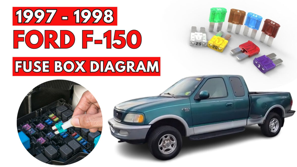

Ford F-150 (1997-1998) Fuse Box Location and Diagrams Guide
This extensive reference shows Ford F-150 (1997–1998) fuse box locations and diagrams. Fuse panels can be accessed and identified to fix electrical faults and maintain your truck.
REPLACING BLOWN FUSES

If electrical components in the vehicle are not working, a fuse may have blown. Blown fuses are identified by a broken element. Check the appropriate fuses before replacing any electrical components.
Even after a fuse is replaced, it may continue to blow if the cause of the overload is not identified and corrected. If a fuse continues to blow, have the vehicle’s electrical system checked. Standard fuse amperage ratings and colors
| Fuse rating | Color |
| 7.5 amp | Brown |
| 10 amp | Red |
| 15 amp | Blue |
| 20 amp | Yellow |
| 30 amp | Light green |
| 30 amp fuse link | Pink |
| 40 amp | Green |
| 60 amp fuse link | Yellow |
| 80 amp fuse link | Black |
| 100 amp fuse link | Blue |
Instrument panel fuses
Always replace a fuse with one that has the specified amperage rating. Using a fuse with a higher amperage rating can cause severe wire damage and could start a fire.


| Position | Amps | Description |
| 1 | 15 | Stop/turn lamps and turn indicators |
| 2 | 5 | Instrument cluster |
| 3 | 25 | Cigarette lighter |
| 4 | 5 | Power mirrors, autolamp, remote
anti-theft/keyless entry, headlamp relay and parking lamp relay |
| 5 | 15 | Speed control, daytime running lamps, climate control blend door, backup lamps, A/C clutch coil |
| 6 | 5 | Brake-shift interlock, generic electronic module (GEM)/central timer module (CTM) and air suspension module |
| 7 | – | Not used |
| 8 | 5 | Radio, remote anti-theft/keyless entry, GEM
module/CTM module |
| Position | Amps | Description |
| 9 | – | Not used |
| 10 | – | Not used |
| 11 | 30 | Wiper system |
| 12 | 5 | On-board diagnostic (OBD II) data link
connector |
| 13 | 15 | Brake ON/OFF switch, rear anti-lock brake module and brake pressure switch |
| 14 | 15 | Interior lamps and accessory delay relay |
| 15 | 5 | GEM module/CTM module |
| 16 | 20 | High beam headlamps |
| 17 | – | Not used |
| 18 | 5 | Instrument illumination |
| 19 | 10 | Air bag diagnostic monitor, instrument cluster |
| 20 | 5 | GEM module/CTM module and powertrain
control module (PCM) |
| 21 | 15 | Starter relay |
| 22 | 10 | Air bag diagnostic monitor and passenger air
bag deactivate switch |
| 23 | 10 | 4WD clutch relay, electronic flasher, 4WD/2WD vacuum solenoids and trailer tow battery charge relay |
| 24 | 10 | I/P blower relay |
| 25 | 5 | 4WABS module and relay |
| 26 | 10 | Right low beam headlamp and DRL module |
| 27 | 5 | Foglamp relay |
| 28 | 10 | Left low beam headlamp |
| 29 | 5 | Autolamp, instrument cluster, transmission
control indicator lamp and switch |
| 30 | 30 | Ignition coils and PCM relay |
| 31 | – | Not used |
| Relays | |
| Position | Description |
| 1 | Interior lamps relay |
| 2 | Battery saver relay |
| 3 | Not used |
| 4 | One touch down relay |
| 5 | Accessory delay relay |
Power distribution box
Lift cover towards left of vehicle to access the power distribution box.
Always disconnect the battery before servicing high current fuses. Always replace the cover to the Power Distribution Box before reconnecting the battery or refilling fluid reservoirs.

| Fuses | ||
| Position | Amps | Description |
| 1 | 20 | Trailer tow back-up and tail lamps |
| 2 | 10 | Air bag diagnostic monitor |
| 3 | 15 | Power locks |
| 4 | 15 | Air suspension |
| 5 | 20 | Horn |
| 6 | 15 | Audio system |
| Fuses | ||
| Position | Amps | Description |
| 7 | 15 | Parking and tail lamps |
| 8 | 30 | Headlamps |
| 9 | 15 | Daytime running lamps and fog lamps |
| 10 | 25 | Auxiliary power point |
| 11 | – | Not used |
| 12 | – | Not used |
| 13 | – | Not used |
| 14 | 60/20 | 4WABS/rear anti-lock brake |
| 15 | 50 | Air suspension compressor |
| 16 | 40 | Trailer tow battery charge and stop/turn lamps |
| 17 | 30 | 4WD transfer case shift motor and clutch |
| 18 | 30 | Driver power seat |
| 19 | 20 | Fuel pump |
| 20 | 50 | Instrument panel fuse panel ignition switch feed |
| 21 | 50 | Instrument panel fuse panel ignition switch feed |
| 22 | 50 | I/P fuse panel battery feed |
| 23 | 40 | I/P blower |
| 24 | 30 | PCM power |
| 25 | 30 | Power windows |
| 26 | – | Not used |
| 27 | – | Not used |
| 28 | 30 | Trailer tow electronic brake |
| 29 | – | Not used |
| Diodes | |
| Position | Description |
| 1 | Rear ABS diode |
| 2 | PCM diode |
| Relays | |
| Position | Description |
| 1 | Windshield wipers HI/LO speed |
| 2 | Windshield wipers run/park relay |
| 3 | Washer pump relay |
| 4 | Fuel pump relay |
| 5 | Horn relay |
| 6 | PCM power relay |
Primary battery fuses (megafuses)
Primary battery fuses are located under the PRIMARY BATTERY FUSE cover next to starter relay.
Ford recommends that megafuses only be serviced by a qualified service technician.

| Location | Amperage | Description |
| 1 | 175 | Power network box megafuse |
| 2 | 175 | Alternator megafuse |
| 3 | 20 | Alternator field minifuse |
Engine minifuse panel
The minifuse panel is located behind the power distribution box.
| Location | Amperage | Description |
| 1 | 5 | Powertrain control module (PCM) |
| 2 | 20 | Trailer tow stop/turn lamps |
| 3 | – | Not used |
| 4 | – | Not used |
| 5 | – | Not used |
| 6 | – | Not used |