


Ford Focus (1999 – 2007) Fuse Box Location and Diagrams Guide
This Guide covers Ford Focus (1999–2007) fuse box locations and schematics, making it easy to find and utilize the right fuses for electrical troubleshooting and repair.
Fuses and Relays
If electrical components in the vehicle are not working, a fuse may have blown. Blown fuses are identified by a broken wire within the fuse. Check the appropriate fuses before replacing any electrical components
Always replace a fuse with one that has the specified amperage rating. Using a fuse with a higher amperage rating can cause severe wire damage and could start a fire.
Changing a fuse
A fuse puller is located in the lid of the auxiliary fuse box.
Fuse Box Locations
Passenger Compartment

This is located on the left-hand side underneath the instrument panel.
Open the glove compartment. Push in both sides of the glove compartment and swivel it down completely.
Engine Compartmen
This is located on the left-hand side of the engine compartment.
To check or replace a fuse, remove the cover of the fuse box by releasing the catch and lifting up.
Passenger Compartment Fuse Box Diagram
Ford Focus (1999)

| Central fuse box | |||
| Fuse | Ampere rating | Colour | Circuits protected |
| 30 | 10 | red | Light switch |
| 31 | 15 | blue | Radio |
| 32 | 15 | blue | Direction indicator (GEM) |
| 33 | 20 | yellow | Horn, power seat |
| 34 | 20 | yellow | Power sunroof |
| 35 | 7.5 | brown | Interior lights, power mirrors |
| 36 | 7.5 | brown | Electronic modules, instrument |
| cluster | |||
| 37 | 25 | white | Power windows, central global |
| closing (left-hand side) | |||
| 38 | 25 | white | Power windows, central global |
| closing (right-hand side) | |||
| 39 | – | – | Not used |
| 40 | 10 | red | Reversing light |
| 41 | 7.5 | brown | Radio (accessory) |
| 42 | 15 | blue | Brake lights |
| 43 | 15 | blue | Power windows, rear screen wiper |
| 44 | 20 | yellow | Front and rear fog lights |
| 45 | 7.5 | brown | Air conditioning, recirculated air |
| 46 | 7.5 | brown | ABS module |
| 47 | 15 | blue | Cigar lighter, centre power point |
| 48 | 10 | red | Data link connector |
| 49 | 25 | white | Heated rear screen |
| 50 | 7.5 | brown | Heated mirrors |
| Central fuse box | |||
| Fuse | Ampere rating | Colour | Circuits protected |
| 51 | – | – | Not used |
| 52 | 15 | blue | Heated front seats |
| 53 | 10 | red | Reversing light, heated washer jets |
| 54 | – | – | Not used |
| 55 | 25 | white | Front power windows |
| 56 | 20 | yellow | Front screen wiper |
| 57 | 7.5 | brown | Side lights right-hand side |
| 58 | 7.5 | brown | Side lights left-hand side |
| 59 | 10 | red | Light switch |
| 60 | 7.5 | brown | Air bag module |
| 61 | 7.5 | brown | Electronic modules, instrument |
| cluster | |||
| 62 | 7.5 | brown | Number plate lights |
| 63 | 20 | yellow | Central locking (on the rear side of |
| the fuse box) | |||
Ford Focus (2000 to 2001)

| Passenger compartment fuse panel | ||
| Fuse | Fuse amp rating | Description |
| 30 | 7 5 | ABS |
| 31 | 15 | Radio |
| 32 | 10 | Light switch |
| 33 | 15 | Hazard flasher |
| 34 | 20 | Horn |
| 35 | 7 5 | Interior lamps, power mirrors |
| 36 | 7 5 | Central timer, electronic modules |
| 37 | Not used | |
| 38 | Not used | |
| 39 | 10 | Back-up lamps |
| 40 | Not used | |
| 41 | Not used | |
| 42 | Not used | |
| 43 | 15 | Rear wiper |
| 44 | 20 | Fog lamps |
| 45 | Not used | |
| 46 | 15 | Cigar lighter |
| 47 | 7 5 | Side lights (left) |
| 48 | 7 5 | Side lights (right) |
| 49 | 25 | Rear defrost |
| 50 | 7 5 | Radio, central timer |
Ford Focus (2002)

| Passenger compartment fuse panel | ||
| Fuse | Fuse amp. rating | Description |
| 30 | 10 | Light switch |
| 31 | 15 | Radio |
| 32 | 15 | Turn signal |
| 33 | 20 | Horn |
| 34 | 20 | Power sunroof |
| 35 | 7.5 | Interior lamps, power mirrors |
| 36 | 7.5 | A/C switch, hazard flasher, instrument cluster |
| 37 | Not used | |
| 38 | Not used | |
| 39 | Not used | |
| 40 | 10 | Back-up lamps (automatic transmission) |
| 41 | 7.5 | Radio and cluster (accessory) |
| 42 | 15 | Stop lamps |
| 43 | 15 | Rear wiper |
| 44 | 20 | Fog lamps |
| 45 | 7.5 | Recirculated air, air conditioning |
| 46 | 7.5 | ABS |
| 47 | 20 | Cigar lighter |
| 48 | 10 | Data link connector |
| 49 | 25 | Rear defrost |
| 50 | Not used | |
| Passenger compartment fuse panel | ||
| Fuse | Fuse amp. rating | Description |
| 51 | Not used | |
| 52 | Not used | |
| 53 | 10 | Back-up lamps (manual transmission), |
| speed control | ||
| 54 | 25 | Rear power windows |
| 55 | 25 | Front power windows |
| 56 | 20 | Front wipers |
| 57 | 7.5 | Position and side lights (right) |
| 58 | 7.5 | Position and side lights (left) |
| 59 | 7.5 | Light switch (headlamps) |
| 60 | 7.5 | Air bag module |
| 61 | 7.5 | PATS modules, instrument cluster |
| 62 | 7.5 | License plate lamp |
| 63 | 20 | Power locks (GEM) (on back side of fuse panel) |
| Relays in the passenger compartment fuse panel | |
| Relay | Description |
| 17 | Starter |
| 18 | Rear intermittent wiper |
| 19 | Front intermittent wiper |
| 20 | Not used |
| 21 | Not used |
| 22 | Not used |
| 23 | Horn |
| 24 | Battery saver |
| 25 | Rear defrost |
Ford Focus (2003 to 2005)

| Fuse/Relay Location | Fuse Amp Rating | Passenger Compartment Fuse Panel Description |
| R17 | — | Starter relay |
| R18 | – | Rear intermittent relay |
| R19 | — | Front wiper intermittent relay |
| R20 | — | Not used |
| R21 | — | Not used |
| R22 | — | Not used |
| R23 | — | Horn relay |
| R24 | — | Battery saver relay |
| R25 | — | Rear defrost relay |
| 30 | 10A | Light switch |
| 31 | 15A | Radio |
| 32 | 15A | Turn signal |
| 33 | 20A | Horn, Power seats (SVT only) |
| 34 | 20A | Power sunroof |
| 35 | 7.5A | Interior lamps, Power mirrors |
| 36 | 7.5A | A/C switch, Hazard flasher, Instrument cluster |
| 37 | —
25A |
Not used (2003)
Decklid/Liftgate release (2004) |
| 38 | — | Not used |
| 39 | — | Not used |
| 40 | 10A | Backup lamps (automatic transaxle) |
| 41 | 7.5A | Radio and cluster (accessory) |
| 42 | 15A | Stop lamps |
| 43 | 15A | Rear wiper |
| 44 | 20A | Fog lamps |
| 45 | 7.5A | Recirculated air, Air conditioning |
| 46 | 7.5A | Anti-lock Brake System (ABS) |
| 47 | 20A | Cigar lighter, Rear power point
(SVT only) |
| Fuse/Relay Location | Fuse Amp Rating | Passenger Compartment Fuse Panel Description |
| 48 | 10A | Data link connector |
| 49 | 25A | Rear defroster |
| 50 | 7.5A | Heated mirror, Heated backlite
indicator |
| 51 | — 7.5A |
Not used (2003 to 2004)
Front passenger sensing system (2005) |
| 52 | 15A | Heated seats |
| 53 | 10A | Backup lamps (manual transaxle) |
| 54 | 25A | Rear power windows |
| 55 | 25A | Front power windows |
| 56 | 20A | Front wipers |
| 57 | 7.5A | Position and side lights (right) |
| 58 | 7.5A | Position and side lights (left) |
| 59 | 7.5A | Light switch (headlamps) |
| 60 | 7.5A | Air bag module |
| 61 | 7.5A | PATS modules, Instrument cluster |
| 62 | 7.5A | License plate lamp |
| 63 | 20A | Power locks (GEM) |
Ford Focus (2006 to 2007)

| Fuse/Relay Location | Fuse Amp Rating | Passenger Compartment Fuse Panel Description |
| R17 | — | Starter relay |
| R18 | — | Not used |
| R19 | — | Not used |
| R20 | — | Not used |
| R21 | — | Daytime running lamps |
| R22 | — | Not used |
| R23 | — | Not used |
| R24 | — | Not used |
| R25 | — | Rear defrost/Heated mirror relay |
| 30 | 10A | Parking lamps |
| 31 | 20A | Radio |
| 32 | 15A | Turn signal (GEM) |
| Fuse/Relay Location | Fuse Amp Rating | Passenger Compartment Fuse Panel Description |
| 33 | 20A | Sunroof |
| 34 | 20A | Horn |
| 35 | 7.5A | A/C switch, Instrument cluster |
| 36 | 7.5A | Interior lamps, Power mirrors |
| 37 | — | Not used |
| 38 | — | Not used |
| 39 | 2A | PCM relay coil |
| 40 | 25A | Rear defroster |
| 41 | — | Not used |
| 42 | 10A | Stop lamps, Shift interlock |
| 43 | 15A | Rear wiper, Sunroof (ignition) |
| 44 | —
15A |
Not used (2006) Daytime Running Lamps (DRL) (2007) |
| 45 | 7.5A | Recirculated air, Air conditioning |
| 46 | — | Not used |
| 47 | 20A | Cigar lighter/Power point |
| 48 | 10A | Data link connector |
| 49 | 7.5A | Heated mirror, Heated backlite
indicator |
| 50 | 10A | Back- up lamps (automatic transaxle
only) |
| 51 | 7.5A | Front passenger sensing system |
| 52 | 15A | Heated seats |
| 53 | 10A | Back-up lamps (manual transaxle only), Speed control |
| 54 | 25A | Rear power windows |
| 55 | 25A | Front power windows |
| 56 | 20A | Front wipers |
| 57 | 7.5A | Radio and cluster (accessory) |
| 58 | — | Not used |
| 59 | 7.5A | Light switch (headlamps) |
| 60 | 7.5A | Air bag module |
| Fuse/Relay Location | Fuse Amp Rating | Passenger Compartment Fuse Panel Description |
| 61 | 7.5A | PATS modules, Instrument cluster |
| 62 | 7.5A | Radio (Start) |
| 63 | 20A | Power locks (GEM) |
Engine Compartment Fuse Box Diagram
Ford Focus (1999)
| Fuses in the auxiliary fuse box | (in the engine compartment) | ||
| Fuse | Ampere rating | Colour | Circuits protected |
| 1 1 | 40 | orange | Main power supply to electrical system |
| 2 | – | – | Not used |
| 3 | 40 | orange | Glow plug heater 2 |
| 4 1 | 50 | red | Heated front screen |
| 5 1 | 60 | blue | Diesel glow plug |
| 6 1 | 30 | green | Engine cooling fan (air conditioning) |
| 7 1 | 40 | orange | Main power supply to electrical system |
| 8 1 | 30 | green | Ignition |
| 9 1 | 20 | yellow | Engine management |
| 10 | 1 | black | Battery voltage sensor |
| 11 | 30 | green | ABS pump |
| 12 | 15 | blue | Fuel pump, diesel injection pump |
| 13 | 30 | green | Headlight washer system |
| 14 | 10 | red | Daytime running lights (parking lights) |
| 15 | 10 | red | A/C clutch solenoid |
| 16 | 15 | blue | Dipped beam left-hand side |
| 17 | 15 | blue | Dipped beam right-hand side |
| Fuses in the auxiliary fuse box | (in the engine compartment) | ||
| Fuse | Ampere rating | Colour | Circuits protected |
| 18 | 10 | red | H02S sensor transmitter |
| (catalytic converter) | |||
| 19 | – | – | Not used |
| 20 | 10 | red | Engine management |
| 21 | 20 | yellow | ABS valves |
| 22 | 20 | yellow | Daytime running lights (Xenon headlights |
| only) | |||
| 23 | 20 | yellow | Auxiliary heater (diesel engine), power sup- |
| ply for battery backup sounder | |||
| (ST170 only) | |||
| 24 | 30 | green | Glow plug heater 1, subwoofer |
| (ST170 only) | |||
| 25 | 15 | blue | Daytime running lights (conventional |
| headlights only) | |||
| 26 | 10 | red | Main beam left-hand side |
| 27 | 10 | red | Main beam right-hand side |
| 28 | 10 | red | Heated front screen, diesel fuel fired heater, |
| diesel engine | |||
| 29 | 30 | green | Engine cooling fan (air conditioning) |
| 64 | 30 | green | Heater blower motor |
| 65 | 30 | green | Engine cooling fan |
Ford Focus (2000 to 2001)

| Power distribution box | ||
| Fuse | Fuse amp. rating | Description |
| 1 | 40 | Main power supply to electrical system |
| 2 | 30 | Engine cooling fan (A/C) 2nd fuse |
| 3 | Not used | |
| 4 | Not used | |
| 5 | Not used | |
| 6 | 50 | Engine cooling fan (A/C) 1st fuse |
| 7 | 40 | Main power supply to electrical system |
| 8 | 30 | Ignition |
| 9 | 20 | Engine management |
| 10 | 10 | Battery voltage sensor, diagnostic plug |
| 11 | 30 | ABS |
| 12 | 15 | Fuel pump |
| 13 | Not used | |
| 14 | Not used | |
| 15 | Not used | |
| 16 | 10 | Low beam (left side) |
| 17 | 10 | Low beam (right side) |
| 18 | 10 | Heated oxygen sensors |
| 19 | Not used | |
| 20 | 10 | Engine management |
| 21 | 20 | ABS |
| 22 | 20 | DRL (low beams) |
| 23 | Not used | |
| 24 | Not used | |
| 25 | Not used | |
| 26 | 10 | High beam (left side) |
| 27 | 10 | High beam (right side) |
| 28 | Not used | |
| 29 | Not used | |
| 64 | 30 | Heater blower motor |
| 65 | Not used | |
| Relays in the power distribution box | |
| Relay | Description |
| 1 | Ignition |
| 2 | Not used |
| 3 | Not used |
| 4 | Not used |
| 5 | High beams |
| 6 | Low beams |
| 7 | Fuel pump |
| 8 | Engine management |
| 9 | Not used |
| 10 | Not used |
| 11 | Air conditioning |
| 12 | Daytime running lights |
| 13 | Fog lamps |
| 14 | Not used |
| 15 | Engine cooling fan level 2 (A/C) |
| 16 | Engine cooling fan level 1 |
Ford Focus (2002 )

| Power distribution box | ||
| Fuse | Fuse amp. rating | Description |
| 1 | 40 | Main power supply to electrical system |
| 2 | 30 | Engine cooling fan (A/C) 2nd fuse |
| 3 | Not used | |
| 4 | Not used | |
| 5 | Not used | |
| 6 | 50 | Engine cooling fan (A/C) 1st fuse |
| 7 | 40 | Main power supply to electrical system |
| 8 | 30 | Ignition switch, starter |
| 9 | 20 | Engine management |
| 10 | 10 | Battery voltage sensor |
| 11 | 30 | ABS |
| 12 | 15 | Fuel pump |
| 13 | Not used | |
| 14 | Not used | |
| 15 | 10 | AC clutch solenoid |
| 16 | 10 | Low beam (left side conventional headlamps) |
| 15 | Low beam (left side HID headlamps) | |
| 17 | 10 | Low beam (right side conventional headlamps) |
| 15 | Low beam (right side HID headlamps) | |
| 18 | 10 | Heated oxygen sensors |
| 19 | Not used | |
| 20 | 10 | Engine module |
| 21 | 20 | ABS |
| 22 | 20 | Low beam (DRL) |
| 23 | Not used | |
| 24 | 30 | MACH 500 subwoofer |
| 25 | 30 | MACH 500 subwoofer |
| 26 | 10 | High beam (left side) |
| 27 | 10 | High beam (right side) |
| 28 | Not used | |
| 29 | Not used | |
| 64 | 40 | Heater blower motor |
| Relays in the power distribution box | |
| Relay | Description |
| 1 | Ignition |
| 2 | Not used |
| 3 | Not used |
| 4 | Not used |
| 5 | High beams |
| 6 | Low beams |
| 7 | Fuel pump |
| 8 | Engine management |
| 9 | Not used |
| 10 | Not used |
| 11 | Air conditioning |
| 12 | Daytime running lights |
| 13 | Fog lamps |
| 14 | Stop lamp inhibit relay (AdvanceTrac® only) |
| 15 | Engine cooling fan level 2 (A/C) |
| 16 | Engine cooling fan level 1 |
Ford Focus (2003 to 2004)
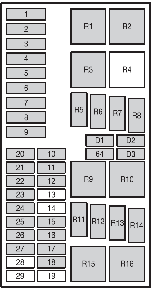
| Fuse/Relay Location | Fuse Amp Rating | Power Distribution Box Description |
| 1 | 40A | Main power supply to electrical
system |
| 2 | 30A | Engine cooling fan (A/C) 2nd fuse |
| 3 | 30A | Cooling fan (2.0L engine only) |
| 4 | 30A | Air pump motor |
| 5 | 30A | Cooling fan 2 (2.0L engine only) |
| 6 | 50A | Engine cooling fan (A/C) 1st fuse |
| 7 | 40A | Main power supply to electrical
system |
| 8 | 30A | Ignition switch, Starter |
| 9 | 20A | Engine management |
| Fuse/Relay Location | Fuse Amp Rating | Power Distribution Box Description |
| 10 | 10A (2.0L engine only) |
Battery voltage sensor |
| 1A (2.3L engine
only) |
||
| 11 | 30A | Anti-lock Brake System (ABS) |
| 12 | 15A | Fuel pump |
| 13 | — | Not used |
| 14 | — | Not used |
| 15 | 10A | A/C clutch solenoid |
| 16 | 10A | Low beam (left side –
conventional headlamps) |
| 15A | Low beam (left side – HID headlamps) |
|
| 17 | 10A | Low beam (right side –
conventional headlamps) |
| 15A | Low beam (right side – HID
headlamps) |
|
| 18 | 10A (2.0L engine only) |
Heated oxygen sensors |
| 15A (2.3L engine
only) |
||
| 19 | — | Not used |
| 20 | 10A | Engine module |
| 21 | 20A | ABS |
| 22 | 20A | Low beam (DRL) |
| 23 | — | Not used |
| 24 | 30A | Subwoofer |
| 25 | — | Not used |
| 26 | 10A
— |
High beam (left)(2003) Not used (2004) |
| 27 | 10A | High beam (right) |
| 28 | — | Not used |
| 29 | — | Not used |
| Fuse/Relay Location | Fuse Amp Rating | Power Distribution Box Description |
| 64 | 40A | Heater blower motor |
| R1 | — | Ignition relay |
| R2 | — | Air pump motor relay |
| R3 | — | Cooling fan (Run-on fan) relay
(2.3L engine only) |
| R4 | — | Not used |
| R5 | — | High beams relay |
| R6 | — | Low beams relay |
| R7 | — | Fuel pump relay |
| R8 | — | Engine management relay |
| R9 | — | Cooling fan relay (2.0L engine
only) |
| R10 | — | Cooling fan 2 relay (2.0L engine only) |
| R11 | — | Air conditioning relay |
| R12 | — | Daytime Running Lamps (DRL)
relay |
| R13 | — | Fog lamps relay |
| R14 | — | HID lamps (SVT only) |
| R15 | — | Cooling fan high speed (A/C only)
relay (2.0L engine only) |
| R16 | — | Cooling fan low speed relay |
| D1 | — | PCM diode |
| D2 | — | Cooling fan diode |
| D3 | — | A/C clutch diode |
Ford Focus (2005)

| Fuse/Relay Location | Fuse Amp Rating | Power Distribution Box Description |
| 1 | 40A | Main power supply (to passenger compartment fuse panel) |
| 2 | 30A | Engine cooling fan (Secondary
fuse) |
| 3 | 40A | Heater blower motor |
| 4 | 30A | Air pump motor (PZEV engine
only) |
| 5 | — | Not used |
| 6 | 50A | Engine cooling fan (Primary fuse) |
| 7 | 40A | Main power supply (to passenger compartment fuse panel) |
| 8 | 30A | Ignition switch, Starter solenoid |
| 9 | 20A | Engine management |
| 10 | 1A | Battery voltage sense |
| Fuse/Relay Location | Fuse Amp Rating | Power Distribution Box Description |
| 11 | 30A | Anti-lock Brake System (ABS)
(pumps) |
| 12 | 15A | Fuel pump |
| 13 | — | Not used |
| 14 | — | Not used |
| 15 | 10A | A/C clutch solenoid |
| 16 | 10A | Low beam (left-hand side) |
| 17 | 10A | Low beam (right-hand side) |
| 18 | 15A | Heated Exhaust Gas Oxygen
(HEGO) sensors |
| 19 | — | Not used |
| 20 | 10A | Engine module (KAP) |
| 21 | 20A | ABS (valves) |
| 22 | 20A | Daytime Running Lights (DRL) |
| 23 | — | Not used |
| 24 | 30A | Subwoofer |
| 25 | — | Not used |
| 26 | 10A | Left high beam |
| 27 | 10A | Right high beam |
| 28 | — | Not used |
| 29 | — | Not used |
| R1 | — | Ignition relay |
| R2 | — | Air pump motor relay (PZEV engine only) |
| R3 | — | Cooling fan (high-speed) |
| R4 | — | Cooling fan (medium-speed) |
| R5 | — | High beams relay |
| R6 | — | Low beams relay |
| R7 | — | Fuel pump relay |
| R8 | — | Engine management relay |
| R9 | — | Cooling fan relay |
| Fuse/Relay Location | Fuse Amp Rating | Power Distribution Box Description |
| R10 | — | Cooling fan relay |
| R11 | — | A/C clutch solenoid relay |
| R12 | — | DRL relay |
| R13 | — | Fog lamps relay |
| R14 | — | Not used |
| R15 | — | Not used |
| R16 | — | Not used |
| D1 | — | PCM diode |
| D2 | — | Cooling fan diode |
| D3 | — | A/C clutch diode |
| D4 | — | Cooling fan diode |
Ford Focus (2006 to 2007)

| Fuse/Relay Location | Fuse Amp Rating | Power Distribution Box Description |
| 1 | 40A | Main power supply (to passenger
compartment fuse panel) |
| 2 | — | Not used |
| 3 | — | Not used |
| 4 | 30A | Air pump motor (PZEV engine only) |
| 5 | 30A | Anti-lock Brake System (ABS)
(pumps) |
| 6 | 50A | Engine cooling fan (Primary fuse) |
| 7 | 40A | Main power supply (to passenger compartment fuse panel) |
| 8 | 30A | Ignition switch, Starter solenoid |
| 9 | 20A | Engine management |
| 10 | 1A | Battery voltage sense |
| 11 | 30A | Subwoofer |
| Fuse/Relay Location | Fuse Amp Rating | Power Distribution Box Description |
| 12 | 15A | Fuel pump motor |
| 13 | 20A | Anti-lock Brake System (ABS)
(valves) |
| 14 | — | Not used |
| 15 | — | Not used |
| 16 | 10A | Low beam (left-hand side) |
| 17 | 10A | Low beam (right-hand side) |
| 18 | 15A | Heated Exhaust Gas Oxygen (HEGO)
sensors |
| 19 | 40A | Heater blower motor |
| 20 | 10A | Engine module (KAP) |
| 21 | 10A | A/C |
| 22 | 20A | Low beams |
| 23 | 15A | High beams, Fog lamps |
| 24 | — | Not used |
| 25 | — | Not used |
| 26 | — | Not used |
| 27 | — | Not used |
| 28 | — | Not used |
| 29 | 10A | ABS module, Speed control |
| R1 | — | Ignition relay |
| R2 | — | High beam relay, Fog lamps relay |
| R3 | — | Cooling fan (high-speed) |
| R4 | — | Cooling fan (low-speed) |
| R5 | — | A/C relay |
| R6 | — | Low beams relay |
| R7 | — | Fuel pump relay |
| R8 | — | Engine management relay |
| R9 | — | Cooling fan relay |
| R10 | — | Cooling fan relay |
| Fuse/Relay Location | Fuse Amp Rating | Power Distribution Box Description |
| R11 | — | Not used |
| R12 | — | Not used |
| R13 | — | Not used |
| R14 | — | Not used |
| R15 | — | Air pump motor relay |
| R16 | — | Not used |
| D1 | — | Not used |
| D2 | — | Not used |
| D3 | — | A/C clutch diode |
| D4 | — | Not used |