
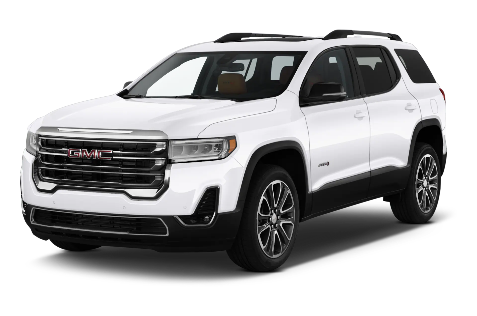

2020 GMC Acadia Fuses and Fuse Box Diagram User Guide
Fuse and fuse box systems protect the 2020 GMC Acadia’s electrical components. This fuse box diagram shows the locations and functions of each fuse to help you troubleshoot and repair your vehicle’s electrical system.
2023 GMC ACADIA Specs, Price, Features and Mileage (Brochure)
Video: 2020 GMC Acadia Fuses
Electrical System
Electrical System Overload
The vehicle has fuses and circuit breakers to protect against an electrical system overload. When the current electrical load is too heavy, the circuit breaker opens and closes, protecting the circuit until the current load returns to normal or the problem is fixed. This greatly reduces the chance of circuit overload and fire caused by electrical problems. Fuses and circuit breakers protect power devices in the vehicle. Replace a bad fuse with a new one of the identical size and rating. If there is a problem on the road and a fuse needs to be replaced, the same amperage fuse can be borrowed. Choose some feature of the vehicle that is not needed to use and replace it as soon as possible.
Headlamp Wiring
An electrical overload may cause the lamps to go on and off, or in some cases to remain off. Have the headlamp wiring checked right away if the lamps go on and off or remain off?
Windshield Wipers
If the wiper motor overheats due to heavy snow or ice, the windshield wipers will stop until the motor cools and will then restart. Although the circuit is protected from electrical overload, overload due to heavy snow or ice may cause wiper linkage damage. Always clear ice and heavy snow from the windshield before using the windshield wipers. If the overload is caused by an electrical problem and not snow or ice, be sure to get it fixed.
Fuses and Circuit Breakers
The wiring circuits in the vehicle are protected from short circuits by a combination of fuses and circuit breakers. This greatly reduces the chance of damage caused by electrical problems.
Danger
Fuses and circuit breakers are marked with their ampere rating. Do not exceed the specified amperage rating when replacing fuses and circuit breakers. Use of an oversized fuse or circuit breaker can result in a vehicle fire. You and others could be seriously injured or killed.
To check a fuse, look at the silver-colored band inside the fuse. If the band is broken or melted, replace the fuse. Be sure to replace a bad fuse with a new one of the identical size and rating. Fuses of the same amperage can be temporarily borrowed from another fuse location if a fuse goes out. Replace the fuse as soon as possible.
Engine Compartment Fuse Block
The underhood fuse block is in the engine compartment, on the driver’s side of the vehicle.

Caution
Do not pull the engine compartment fuse block lever, since it is intended only for service purposes. If pulled, vehicle malfunction may occur. Spilling liquid on any electrical component of the vehicle may damage it. Always keep the covers on any electrical component.
To remove the fuse block cover, press the clips on the cover and lift it straight up. The vehicle may not be equipped with all of the fuses, relays, and features shown.

| Fuse | Usage |
|---|---|
| F1 | Antilock brake system |
| F2 | Starter 1 |
| F3 | DC-DC transformer 1 |
| F4 | – |
| F5 | DC-DC transformer 2 |
| F6 | Amplifier 1 |
| F7 | Front blower |
| F8 | Starter 3 |
| F9 | – |
| F10 | – |
| F11 | – |
| F12 | Front wiper |
| F13 | Starter 2 |
| F14 | LED/Automatic headlamp leveling |
| F15 | Rear wiper 1 |
| F16 | – |
| F17 | – |
| F18 | Automatic headlamp leveling module |
| F19 | – |
| F20 | – |
| F21 | – |
| F22 | Electronic brake control module |
| F23 | Parking/Trailer lamps |
| F24 | Right trailer stop lamp/Turn lamp |
| F25 | Steering column lock |
| F26 | – |
| F27 | Left trailer stoplamp/Turn lamp |
| F28 | – |
| F29 | – |
| F30 | Washer pump |
| F31 | – |
| F32 | – |
| F33 | Fog lamps |
| F34 | Horn |
| F35 | – |
| F36 | Headlamp high-beam left |
| F37 | Headlamp high-beam right |
| F38 | Automatic headlamp leveling motor |
| F39 | Transmission control module 1/Battery 1 |
| F40 | Left rear bus electrical center/Ignition |
| F41 | Instrument cluster |
| F42 | Heating, ventilation, and air conditioning |
| F43 | Head-Up Display |
| F44 | Electronic brake control module electric brake |
| F45 | – |
| F46 | – |
| F47 | – |
| F48 | Rear wiper 2 |
| F49 | Interior rearview mirror/Trailer |
| F50 | Fuel system control module |
| F51 | Heated steering wheel |
| F52 | Air conditioning clutch |
| F53 | – |
| F54 | Coolant pump |
| F55 | – |
| F56 | – |
| F57 | Engine control module/Ignition |
| F58 | Transmission control module/Ignition |
| F59 | Engine control module battery |
| F60 | – |
| F61 | O2 sensor 1/Aeroshutter |
| F62 | Engine control module – odd |
| F63 | O2 sensor 2 |
| F64 | Engine control module – even |
| F65 | Engine control module powertrain 1 |
| F66 | Engine control module powertrain 2 |
| F67 | Engine control module powertrain 3 |
| F68 | – |
| F69 | – |
| F70 | – |
| F71 | – |
| F72 | – |
| F73 | – |
| F74 | – |
| F75 | – |
| F76 | – |
| F77 | – |
| Relay | Usage |
|---|---|
| K1 | Starter 1 |
| K2 | Run/Crank |
| K3 | Starter 3 |
| K4 | LED/Automatic headlamps |
| K5 | – |
| K6 | Coolant pump |
| K7 | Engine control module |
| K8 | Air conditioning |
| K9 | – |
| K10 | Starter 2 |
Instrument Panel Fuse Block

The instrument panel fuse block is inside the center console on the passenger side of the vehicle. Open the fuse panel door, or remove the panel from the passenger side by pulling it out.

To reinstall the door, push the door back into its original location.

The vehicle may not be equipped with all of the fuses, relays, and features shown.
| Fuses | Usage |
|---|---|
| F1 | Body Control Module 6 |
| F2 | Diagnostic link/Central gateway module |
| F3 | Electric steering column lock |
| F4 | – |
| F5 | Logistics |
| F6 | Heating, ventilation, and air conditioning |
| F7 | Body control module 3 |
| F8 | – |
| F9 | Front passenger heated seat |
| F10 | Airbag/Seat belt |
| F11 | – |
| F12 | Amplifier |
| F13 | Body Control Module 7 |
| F14 | Driver heated seat |
| F15 | Instrument panel switch bank |
| F16 | Sunroof |
| F17 | Body control module 1 |
| F18 | Instrument cluster |
| F19 | – |
| F20 | Rear seat entertainment |
| F21 | Body control module 4 |
| F22 | Infotainment USB data/Aux jack |
| F23 | Body control module 2 |
| F24 | USB charger/Wireless charging |
| F25 | Park aid/Electronic range select |
| F26 | CIM |
| F27 | Video |
| F28 | Heating, ventilation, and air conditioning display |
| F29 | Radio |
| F30 | Steering wheel adjustment controls |
| F31 | Electronic brake control module electric brake booster |
| F32 | DC AC inverter |
| F33 | Driver power seat |
| F34 | Passenger power seat |
| F35 | Battery IEC 1 feed |
| F36 | Electric power steering |
| F37 | Rear seat entertainment/USB charge/Wireless charging module |
| F38 | Body Control Module 8 |
| F39 | – |
| Circuit Breakers | Usage |
|---|---|
| F40 | – |
| F41 | – |
| F42 | Auxiliary power outlet/Lighter |
Rear Compartment Fuse Block

The rear compartment fuse block is behind a trim panel on the driver side of the rear storage compartment.

Remove the side bin, load the floor, and foam. Remove the trim plate to access the fuse block. The label for this fuse block is in the spare tire area, on the foam under the cargo floor.

| Fuses | Usage |
|---|---|
| F1 | – |
| F2 | Trailer battery 1 |
| F3 | Driver seat belt motor |
| F4 | Rear blower |
| F5 | Rear drive control |
| F6 | Passenger seat belt motor |
| F7 | Right window |
| F8 | Rear defogger |
| F9 | Left window |
| F10 | – |
| F11 | Trailer reverse |
| F12 | – |
| F13 | – |
| F14 | – |
| F15 | – |
| F16 | – |
| F17 | Camera/Spare |
| F18 | Trailer module |
| F19 | Ventilated seats |
| F20 | – |
| F21 | Trailer connector |
| F22 | – |
| F23 | – |
| F24 | Passenger window switch |
| F25 | – |
| F26 | Trailer brake |
| F27 | Driver ventilated seat/Lumbar |
| F28 | Passive entry/Passive start |
| F29 | – |
| F30 | Canister vent |
| F31 | – |
| F32 | Heated mirror |
| F33 | – |
| F34 | Liftgate module |
| F35 | Fuel system control module |
| F36 | Passenger ventilated seat/Lumbar |
| F37 | – |
| F38 | Window module |
| F39 | Rear closure |
| F40 | Memory seat module |
| F41 | Automatic occupancy sensor |
| F42 | Trailer battery 2 |
| F43 | – |
| F44 | – |
| F45 | Liftgate motor |
| F46 | Rear heated seats |
| F47 | – |
| F48 | Glass break sensor |
| F49 | – |
| F50 | – |
| F51 | – |
| F52 | Active dampening system module |
| F53 | Rear parking aid module/Video/USB/Spare |
| F54 | External object calculating/Side blind zone alert |
| F55 | – |
| F56 | Universal remote system/Rain sensor |
| F57 | Theft deterrent |
| Circuit Breakers | Usage |
|---|---|
| CB1 | – |
| CB2 | – |
| CB3 | Rear auxiliary power outlet |
| Relays | Usage |
|---|---|
| K1 | – |
| K2 | – |
How to replace the fuses in a GMC Acadia:
- Locate the Fuse Box: The fuse box in a GMC Acadia is typically located in the engine compartment or under the dashboard on the driver’s side. Look for a rectangular black box with a removable lid.
- Identify the Blown Fuse: Before replacing any fuses, it’s essential to identify which fuse has blown. Inspect the fuse box cover for a diagram that indicates the location and function of each fuse. Use a flashlight if needed for better visibility.
- Turn Off the Vehicle: Ensure that the vehicle’s engine is turned off and the key is removed from the ignition to prevent any electrical mishaps while working on the fuses.
- Remove the Fuse Puller Tool: Most fuse boxes come with a fuse puller tool attached to the lid or located inside the fuse box. If available, use the fuse puller tool to carefully remove the blown fuse.
- Replace the Blown Fuse: Once the blown fuse is identified and the fuse puller tool is in hand, grasp the blown fuse firmly with the puller tool and carefully pull it straight out from its slot in the fuse box.
- Inspect the Fuse: Take a moment to inspect the blown fuse visually. If the fuse wire inside is broken or damaged, it’s a clear indication that the fuse needs to be replaced.
- Insert the Replacement Fuse: With the new fuse in hand, carefully align it with the corresponding slot in the fuse box and gently push it into place until it’s fully seated.
- Test the Circuit: After replacing the fuse, turn the ignition key to the accessory position (without starting the engine) and test the electrical component associated with the fuse to ensure it’s functioning properly.
- Secure the Fuse Box Lid: Once you’ve verified that the electrical component is working correctly, securely reattach the lid to the fuse box to protect the fuses from dust and moisture.
Tips:
- Always use the correct amperage replacement fuse to avoid damaging the electrical system.
- Keep spare fuses of various amperages in your vehicle’s emergency kit for quick replacements on the road.
FAQs
The fuse system in the 2020 GMC Acadia comprises fuses, relays, and corresponding diagrams for efficient electrical circuit protection and troubleshooting.
A blown fuse can be identified by inspecting the fuse for a broken or damaged fuse wire, or by using the fuse box diagram to locate the affected fuse.
The fuse box in the 2020 GMC Acadia is typically located in the engine compartment or under the dashboard on the driver’s side for easy access.
Relay and fuse diagrams serve as visual guides to help drivers identify the location and function of specific fuses and relays within the vehicle’s electrical system.
Useful Links
View Full PDF: GMC Acadia 2020 User Manual | Auto User Guide
2023 GMC ACADIA Specs, Price, Features and Mileage (Brochure)
Display Setting: 2020 GMC Acadia Warning Messages Guide