
MINI Cooper (2006 – 2015) Fuse Box Diagrams & Location
The MINI Cooper (2006–2015) features several fuse boxes that protect essential electrical systems throughout the vehicle. Knowing their locations and fuse assignments makes it easier to identify electrical issues, replace blown fuses, and maintain reliable operation of lights, accessories, safety systems, and other important components.
Fuse Box Location
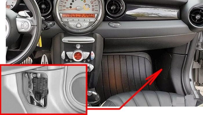
Passenger Compartment Fuse Box
The fuse box is located on the right side of the footwell, in the side trim.
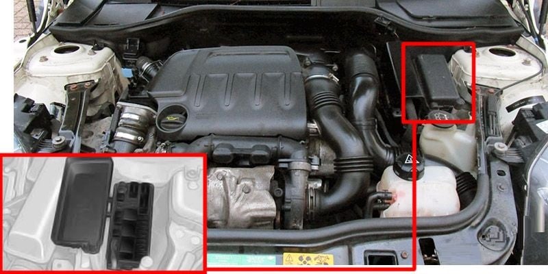
Engine Compartment Fuse Box
Press the latch to open.
Fuse Box Diagrams
Passenger Compartment Fuse Box
MINI Cooper (2006 – 2008)

| № | Amps | Protected Component |
|---|---|---|
| 1 | – | – |
| 2 | 20A | Trailer Socket |
| 3 | 30A | Headlight Washer Relay, Headlight Washer Pump Relay |
| 4 | 30A | Trailer Module |
| 5 | 30A | Footwell Module |
| 6 | 20A | Amplifier |
| 6 | 30A | R57: Convertible Top Module |
| 7 | 30A | Sunroof |
| 8 | 30A | Footwell Module |
| 9 | 15A | Driver’s Door System Lock, Passenger’s Door System Lock, Fuel Filler Flap Central Locking |
| 10 | 10A | Telephone (Base Plate, ULF-SBX-H or ULF SBX) or Telephone Retrofit Packages Connector |
| 11 | 10A | Video Module, Digital Tuner US, Satellite Receiver, Digital Tuner, Navigation (Japan) |
| 12 | 10A | CD Changer |
| 13 | 15A | Transmission Control |
| 14 | 10A | Make-Up Mirror Lights, Roof Operating Unit, Luggage Compartment Light |
| 15 | 10A | Steering Column Switch Centre |
| 16 | 5A | Dynamic Stability Control (DSC) |
| 17 | 5A | Rain/Headlight Sensor, Tyre Pressure Control (RDC), Hydraulic Shift Unit (Automatic Transmission), Selector Lever Position Switch (Automatic Transmission), DC/DC Converter (Manual Transmission) |
| 18 | 10A | Heating/Air Conditioning System, Glove Compartment Light |
| 19 | 10A | Control Access Control Unit |
| 20 | 7.5A | Outside Mirror Fold-in |
| 21 | 10A | MINI Joystick, Radio, Central Information Display (with CCC/M-ASK) |
| 22 | 15A | Rear Wiper Relay, Rear Wiper Motor |
| 23 | 10A | A/C Compressor Clutch Relay |
| 24 | 15A | Windscreen Washer Pump |
| 25 | 5A | Electrochromic Interior Rearview Mirror, Selector Lever Position Switch (USA, Canada, Australia) |
| 26 | 7.5A | Siren with Tilt Alarm Sensor |
| 27 | 5A | OBD II Socket |
| 28 | 15A | Driver’s Door System Lock, Passenger’s Door System Lock, Fuel Filler Flap Cantral Locking Drive (EU) |
| 29 | 5A | Telephone Retrofit Packages Connector |
| 30 | 5A | Park Distance Control (PDC) |
| 31 | 5A | AUC Sensor, DC/DC Converter N47: Fuel Heater, Electric Auxiliary Heater W16: Electric Auxiliary Heater, Telephone Retrofit Packages Connector |
| 32 | 7.5A | Mirror Adjustment Switch, Driver’s Seat Heating Module, Passenger’s Seat Heating Module, Electrochromic Interior Rearview Mirror |
| 33 | 5A | DSC Sensor |
| 34 | 5A | Car Access System |
| 35 | – | – |
| 36 | 5A | Japan: Navigation |
| 37 | 5A | Additional Instrument |
| 38 | 30A | Rear Window Defogger Relay |
| 39 | 30A | Passenger’s Seat Heating Module |
| 40 | 30A | Driver’s Seat Heating Module |
| 41 | – | – |
| 42 | 20A | Front Cigar Lighter, Rear Charging Socket |
| 43 | 20A | Fuel Pump Relay |
| 44 | 20A | Horn Relay, Steering Column Switch Centre |
| 45 | 20A | Radio, Central Information Display (with CCC/CHAMP) |
| 46 | 20A | Heating/Air Conditioning System (except IHKA), Blower Motor (IHKA), Blower Output Stage (IHKA) |
| 47 | 40A | Footwell Module |
| 48 | 40A | Footwell Module |
| 49 | 40A | Car Access System |
MINI Cooper (2009 – 2015)
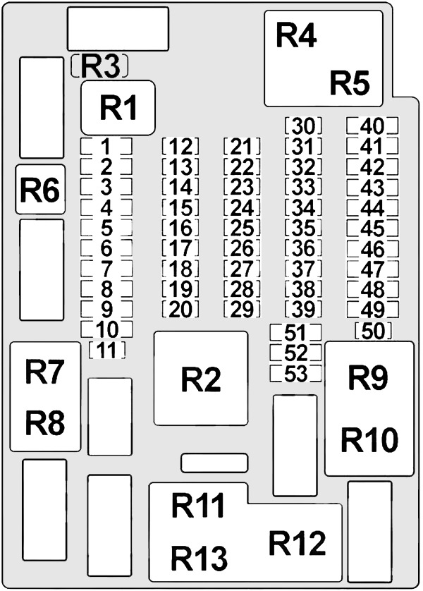
| № | Amps | Protected Component |
|---|---|---|
| 1 | – | – |
| 2 | 30A | Headlight Washer Relay, Headlight Washer Pump Relay |
| 3 | 30A | Trailer Module |
| 4 | 30A | Footwell Module |
| 5 | 20A | 2009: Amplifier |
| 6 | 30A | Sunroof R57: Convertible Top Module |
| 7 | 20A | Trailer Socket |
| 8 | 30A | Footwell Module |
| 9 | 30A | Rear Driver’s Side Power Window Motor, Rear Passenger’s Side Power Window Motor |
| 10 | 30A | R57: Rear Right Power Window Motor |
| 11 | 15A | Driver’s Door System Lock, Passenger’s Door System Lock, Fuel Filler Flap Central Locking (USA) |
| 12 | 5A | 2009-2011: Telephone (Base Plate, ULF-SBX-H or ULF SBX) or Telephone Retrofit Packages Connector 2011-2015: Telephone (Base Plate, USB Hub) or Combox |
| 13 | 10A | 2009-2010: Video Module, Digital Tuner US, Satellite Receiver, Digital Tuner |
| 13 | 10A | Japan: Navigation |
| 14 | 10A | 2009-2010: CD Changer |
| 15 | 15A | Transmission Control |
| 16 | 10A | Make-Up Mirror Lights, Roof Operating Unit, Luggage Compartment Light |
| 17 | 10A | Steering Column Switch Centre |
| 18 | 5A | Dynamic Stability Control (DSC) |
| 19 | 5A | Rain/Headlight Sensor, Tyre Pressure Control (RDC), Hydraulic Shift Unit (Automatic Transmission), Selector Lever Position Switch (Automatic Transmission), DC/DC Converter (Manual Transmission) |
| 20 | 10A | Heating/Air Conditioning System, Glove Compartment Light |
| 21 | 10A | Control Access Control Unit |
| 22 | 7.5A | Outside Mirror Fold-in |
| 23 | 10A | MINI Joystick, Radio (2009-2010), Central Information Display (with CCC/M-ASK) |
| 24 | 10A | A/C Compressor Clutch Relay |
| 25 | 15A | Windscreen Washer Pump |
| 26 | 5A | Electrochromic Interior Rearview Mirror, Selector Lever Position Switch (USA, Canada, Australia) |
| 27 | 7.5A | Siren with Tilt Alarm Sensor |
| 29 | 5A | OBD II Socket, Additional Instrument |
| 30 | 15A | High Beam Headlight Relay (Xenon) |
| 31 | 5A | 2009-2010: Telephone Retrofit Packages Connector N47: Fuel Heater, Electric Auxiliary Heater W16: Electric Auxiliary Heater, Telephone Retrofit Packages Connector |
| 32 | 5A | Park Distance Control (PDC) |
| 33 | 5A | AUC Sensor, DC/DC Converter |
| 34 | 7.5A | Mirror Adjustment Switch, Driver’s Seat Heating Module, Passenger’s Seat Heating Module, Electrochromic Interior Rearview Mirror |
| 35 | 5A | DSC Sensor |
| 36 | 5A | Car Access System |
| 37 | – | – |
| 38 | 5A | Japan: Navigation |
| 39 | 5A | USB Hub, Navigation (Asia) |
| 40 | 30A | Rear Window Defogger Relay |
| 41 | 30A | Passenger’s Seat Heating Module |
| 42 | 30A | Driver’s Seat Heating Module |
| 43 | 20A | Trailer Module |
| 43 | 10A | R57: Rollover Protection Controller |
| 44 | 20A | Front Cigar Lighter, Rear Charging Socket |
| 45 | 20A | Radio, Central Information Display (with CCC/CHAMP) |
| 46 | 20A | Fuel Pump Relay |
| 47 | 20A | Horn Relay, Steering Column Switch Centre |
| 48 | 30A | Heating/Air Conditioning System (except IHKA), Blower Motor (IHKA), Blower Output Stage (IHKA) |
| 49 | 30A/40A | Amplifier / Car Access System |
| 50 | 15A | Rear Wiper Relay |
| 51 | 40A | Car Access System |
| 52 | 40A | Footwell Module |
| 53 | 40A | Footwell Module |
Engine Compartment Fuse Box
Main Fuse Box
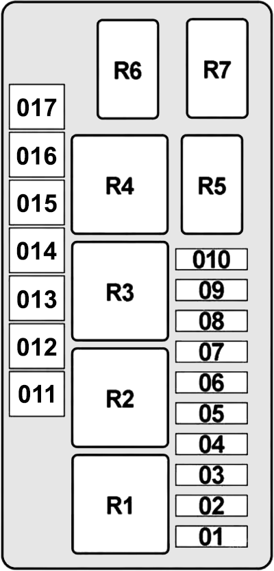
| № | Amps | Protected Component |
|---|---|---|
| 1 | 5A/7.5A | Digital Motor Electronics (DME) Control Unit |
| 2 | 25A | N12, N14, N16, N18: Digital Motor Electronics (DME) Control Unit |
| 3 | 20A | N12, N14, N16, N18: Digital Motor Electronics (DME) Control Unit, Crankcase Ventilation Heater Relay |
| 4 | 20A | N12, N14, N16, N18: Digital Motor Electronics (DME) Control Unit |
| 5 | 5A/7.5A | Diagnostic Module for Fuel Tank Leakage, Electric Fan Relay, Fuel Injectors Relay (Cooper S), Valvetronic Relay (except Cooper S) |
| 6 | 25A | Dynamic Stability Control (DSC) |
| 7 | 7.5A | Crankcase Ventilation Heater Relay (Engine Breather Heater) W16: Additive Pump Relay |
| 8 | 30A/40A | Electric Fan Relay (Electric Fan) |
| 9 | 25A/30A | Wiper Relay №1 & 2 |
| 10 | 15A/20A | N12, N14 (2006-2015), N16, N18 (2007-2015): Terminal 15 Relief Relay (Electronics Junction Box, Digital Motor Electronics (DME) Control Unit) N16, N18 (2006-2007): Digital Motor Electronics (DME) Control Unit W16: Fuel Heater, Electronics Junction Box |
| 11 | 40A | Dynamic Stability Control (DSC) |
| 12 | 50A | N47: Fuel Heater |
| 13 | 30A | 2006-2007: Dynamic Stability Control (DSC) |
| 14 | 50A | N12, N14, N16, N18: Electric Fan Relay №2 (Electric Fan, Digital Motor Electronics (DME) Control Unit) W16, N47: Electric Fan Relay №2 (Electric Fan, Digital Diesel Electronics (DDE) Control Unit) |
| 15 | 50A | Windscreen Heater Relay |
| 16 | – | – |
| 17 | 30A | DC/DC Converter |
| Reverse Side: | ||
| 1 | – | – |
| 2 | 60A | W16, N47: Preheating Control Unit |
| 3 | 40A | R57: Convertible Top Relay №1 & 2 |
| 4 | 80A | Electromechanical Power Steering |
| 5 | – | – |
Additional Fuse Box No 1
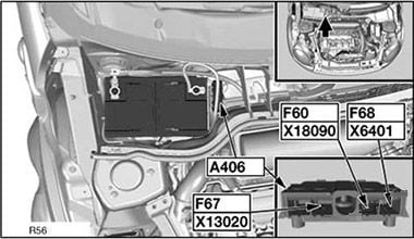
| № | Amps | Protected Component |
|---|---|---|
| 60 | 125A | Passenger Compartment Fuse Box |
| 67 | 150A | Engine Compartment Fuse Box |
| 68 | 40A | Cooper S: Fuel Injectors Relay except Cooper S: Valvetronic Relay |
| 69 | 100A | N47, W16: Electric Auxiliary Heater |
Additional Fuse Box №2 (diesel)
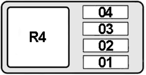
| № | Amps | Protected Component |
|---|---|---|
| 1 | 25A | N47: Digital Diesel Electronics (DDE) Control Unit W16: Boost Pressure Actuator (Pressure Converter), Throttle Valve, Volume Control Valve, Intercooler Bypass Actuator |
| 2 | 25A | N47: Changeover Valve for EGR Valve, Volume Control Valve, Preheating Control Unit, Exhaust Recirculation Cooler Bypass Solenoid Valve, Oxygen Sensor after Catalytic Converter, Oxygen Sensor before Catalytic Converter, Hot-Film Air Mass Meter, Camshaft Hall-Effect Sensor, Rail Pressure Control Valve W16: Digital Diesel Electronics (DDE) Control Unit |
| 3 | 5A | N47: Electric Fan Relay W16: Additive Pump Relay, Electric Fan Relay |
| 4 | 5A | Digital Motor Electronics (DME) Main Relay |
Related Posts: