


Renault Clio (2006 – 2012) Fuse Box Diagrams & Location User Guide
The Renault Clio (2006–2012) has numerous fuse boxes to protect important electrical systems. To accurately diagnose problems, repair blown fuses, and maintain your vehicle’s electrical components, this guide includes clear diagrams and fuse box locations.
Fuse Box Locations
Engine Compartment Fuse Box

Passenger Compartment Fuse Box

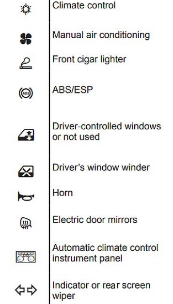
Depending on the vehicle, open the cover to the right of the steering wheel or the glove box. To identify the fuses, refer to the fuse allocation symbols.

Instrument Panel Diagram
Renault Clio (2006 to 2012)
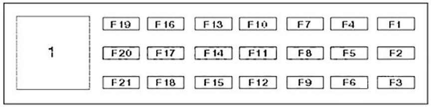
| No | Description | |
|---|---|---|
| 1 | Ignition main circuits relay 1 | |
| F1 | 30A | Indicators (without keyless entry system) |
| F1 | 15A | Rear screen wiper motor (with keyless entry system) |
| F2 | 15A | AC control module, auxiliary equipment, instrument panel |
| F3 | 7,5A | Door mirror control module, interior lamps, vanity mirror lamps |
| F4 | 15A | Data link connector (DLC), horns |
| F5 | – 10A |
Not used (with keyless entry system) Glove box lamp, load area lamp (without keyless entry system) |
| F6 | 25A | Central locking, electric window motor, driver |
| F7 | – 25A |
Not Used (with keyless entry system) Electric window dual switch, driver’s door (without keyless entry system) |
| F8 | 10A | ABS control module |
| F9 | 15A | Cigarette lighter |
| F10 | 20A | AC/heater blower motor control module (manual temperature control) |
| F11 | 20A | AC/heater blower motor control module (automatic temperature control) |
| F12 | 15A | AC control module, AC/heater function control panel, alarm system horn, audio unit, fuse box/relay plate, fascia 2-relay 6/7, heated seats, multifunction control module, rear screen washer pump, steering wheel function control module, telephone control module, wind screen washer pump |
| F13 | 10A | Brake pedal position (BPP)switch, fuse box/relay plate, fascia 2- relay 3 |
| F14 | – 5A |
Not used (with keyless entry system) Light sensor, door mirror control module, interior lamps, rain sensor, vanity mirror lamps, windscreen wiper (without keyless entry system) |
| F15 | – 20A |
Not used (with keyless entry system) Rear screen wiper motor (without keyless entry system) |
| F16 | 30A 15A |
Indicators (with keyless entry system) Immobilizer control module (without keyless entry system) |
| F17 | 30A | Central locking |
| F18 | 15A | Door mirror control module, interior lamps, vanity mirror lamps (with keyless entry system) Multifunction control module (without keyless entry system) |
| F19 | 5A | In-car temperature sensor blower |
| F20 | 25A | Electric window motor, passenger |
| F21 | Electric window diode, rear |
Consumer Cut-out fuses Diagram
Renault Clio (2006 to 2012)

| No | A | Description |
|---|---|---|
| 1 | Electric window relay, driver | |
| 2 | – | |
| 3 | Stop lamps relay | |
| 4 | – | |
| 5 | – | |
| 6 | Electric window relay – rear 1 | |
| 7 | Electric window relay – rear 2 | |
| F1 | – | |
| F2 | 20A | Heated seats |
| F3 | 15A | Sunroof |
| F4 | 25A | Electric windows, rear |
| F5 | – | |
| F6 | – |
Engine Compartment Diagram
Renault Clio (2006 to 2012)

| No | Amp | Description |
|---|---|---|
| 1 | Heated rear window relay | |
| 2 | Engine control (EC) relay- except K9K764 | |
| 3 | Headlamp low beam relay | |
| 4 | Fog lamps relay | |
| 5 | Starter motor relay | |
| 6 | – | |
| 7 | Engine coolant blower motor relay, high-speed 1 | |
| 8 | Engine coolant blower motor relay, lowspeed2 | |
| 9 | Ignition main circuits relay2 | |
| F1 | 25A | ABS control module |
| F2 | – | |
| F3 | 10A | Headlamp high beam, right |
| F4 | 10A | Headlamp high beam, left |
| F5 | 10A | AC control module, central locking, cruise control selector switch, electric window motor, rear right, ABS/ESP system, multifunction display, RH side lamps, RH tail lamps |
| F6 | 10A | Audio unit, central locking, cigarette lighter, door mirror adjustment switch, electric window dual switch, driver’s door, electric window motor, rear left, electric window switch, passenger door, headlamp adjustment control module, licence plate lamp, parking aid, LH side lamps, LH tail lamps, traction control system (TCS) |
| F7 | 15 A | Auxiliary heater relay 1/2, cruise control reversing switch, data link connector (DLC), electric power steering, gas discharge headlamps control module, multifunction control module, transmission mode selection switch, transmission selectorlamp, tyre pressure monitor control module |
| F8 | 20A | Windscreen wiper motor |
| F9 | 15A | Headlamp adjustment motor, right, headlamp low beam, right |
| F10 | 15A | Headlamp adjustment motor, left, headlamp low beam, left |
| F11 | 10A | AC compressor clutch |
| F12 | – | – |
| F13 | 25A | Starter motor solenoid |
| F14 | 20 A | Transmission control module (TCM) |
| F15 | – | – |
| F16 | 15A | Heated rear window |
| F17 | 15A | Headlamp washer pump relay |
| F18 | 5 A | Transmission control module (TCM) |
| F19 | – | – |
| F20 | 10A | Reversing lamps |
| F21 | 20A | Ignition coils |
| F22 | 20 A | Engine control module(ECM) |
| F23 | 10 A | Supplementary restraint system (SRS) control module |
| F24 | 10 A | Engine control module(ECM), steering column lock solenoid – with keyless entry system |
| F25 | 20A | Front fog lamps |
Power Supply Fuse Box Diagram
Renault Clio (2006 to 2012)

| No | A | Description |
|---|---|---|
| 1 | Headlamp washer pump relay 1 | |
| 2 | Headlamp washer pump relay 2 | |
| 3 | Gas discharge headlamp relay | |
| F1 | 30A | Engine control (EC)relay- K9K764 |
| F2 | 30A | Transmission pump relay- D4F764(sequential mechanical gearbox) |
| F3 | 30A | Engine coolant blowermotor-K9K766,D4F764 (sequential mechanical gearbox) |
| F4 | 30A | Engine coolant blower motor -K4M, K4J, D4F(MT) |
| F5 | 50A | Fuse box/relay plate, fascia 2-fuses F2-F4 |
| F6 | 80A | Auxiliary heater 1/2 |
| F7 | – | |
| F8 | 50A | ABS control module |
| F9 | – | |
| F10 | – | |
| F11 | – | |
| F12 | 10A | Gas discharge headlamp relay |
Main Fuses Diagram
Renault Clio (2006 to 2012)

| No | Amp | Description |
|---|---|---|
| F1 | 350A | Fuse box/relay plate, engine bay 2-fuses F2-F8, fuse box/relay plate, engine bay 3-fuses F2/F3 |
| F2 | 70A | Fuse box/relay plate, fascia 1 -fuses F16-F18, fuse box/relay plate, engine bay 2-fuse F1 |
| F3 | 60A | Electric power steering |
| F4 | 70A | Fuse box/relay plate, fascia 1 – fuses F1-F6/F20, relay 1 |
| F5 | 60A | Multifunction control module |