
BAIC EU5 PLUS 2024 Fuse Box Diagrams & Location
The BAIC EU5 PLUS 2024 uses fuse boxes to protect important electrical circuits and components. Knowing the correct fuse locations and assignments makes troubleshooting electrical problems easier. This guide covers fuse box locations, diagrams, fuse ratings, and protected components for the BAIC EU5 PLUS.
Fuse Box Location
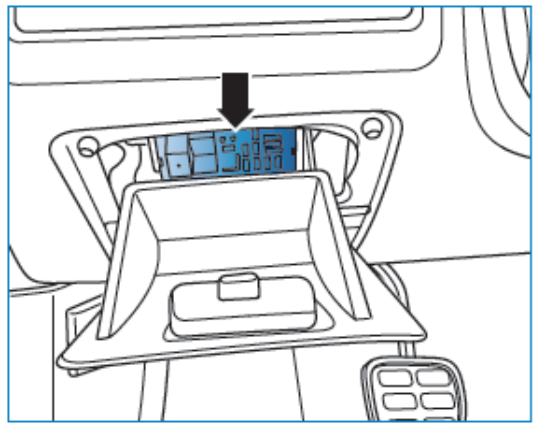
Passenger Compartment Fuse Box
The IPJB is located at the lower left trim panel of the instrument panel.
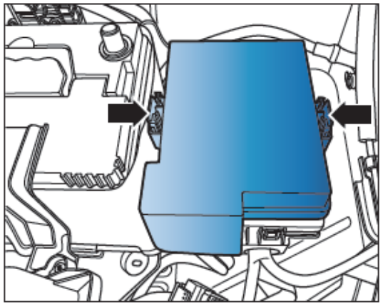
Engine Compartment Fuse Box
The engine compartment fuse box is located on the right side of the battery.
Fuse Box Diagrams
Passenger Compartment Fuse Box
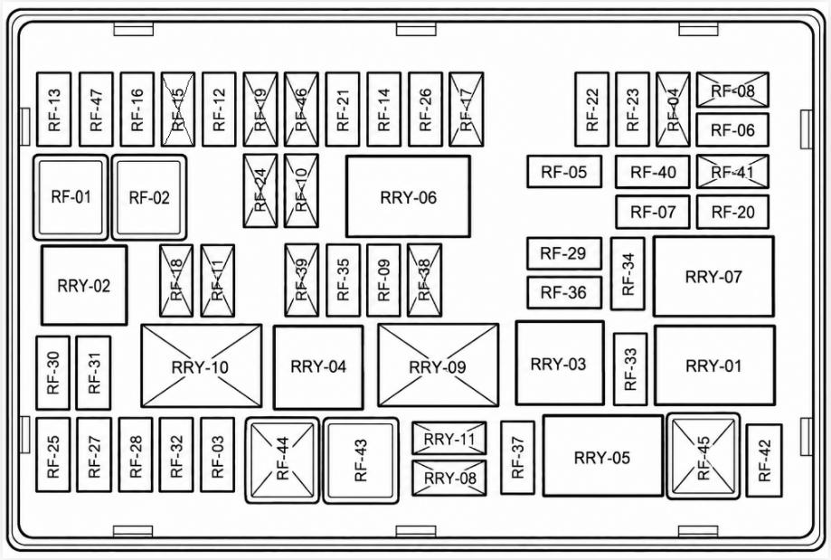
| No. | Specification | Protection Circuit |
|---|---|---|
| RRY-01 | – | Rear windshield heating relay |
| RRY-02 | – | Reversing lamp relay |
| RRY-03 | – | Rear fog lamp relay |
| RRY-04 | – | Daytime running lamp relay |
| RRY-05 | – | ACC relay |
| RRY-06 | – | IG1 relay |
| RRY-07 | – | IG2 relay |
| RRY-08 | – | Reserved |
| RRY-09 | – | Reserved |
| RRY-10 | – | Reserved |
| RRY-11 | – | Reserved |
| RF01 | 30A | Front left window |
| RF02 | 30A | Right front window |
| RF03 | 20A | Power lock |
| RF04 | 5A | Inner ambient light |
| RF05 | 15A | POWER-C-LIGHTING2 |
| RF06 | 30A | AM1 |
| RF07 | 20A | AM2 |
| RF08 | – | Reserved |
| RF09 | 10A | Left front fog lamp |
| RF10 | – | Reserved |
| RF11 | – | Reserved |
| RF12 | 5A | EMS |
| RF13 | 5A | TCU power supply |
| RF14 | 5A | ISSOFF/TCU/BCM/PEPS |
| RF15 | – | Reserved |
| RF16 | 7.5A | Brake switch |
| RF17 | – | Reserved |
| RF18 | – | Reserved |
| RF19 | – | Reserved |
| RF20 | 7.5A | Rainfall sensor |
| RF21 | 10A | Reversing lamp |
| RF22 | 5A | BCM ACC electricity |
| RF23 | 15A | Cigarette lighter power supply |
| RF24 | – | Reserved |
| RF25 | 15A | Radio |
| RF26 | 20A | Sunroof motor |
| RF27 | 15A | Power alarm |
| RF28 | 7.5A | Trunk lamp |
| RF29 | 7.5A | ESCL IMMO |
| RF30 | 7.5A | PEPS |
| RF31 | 10A | PEPS |
| RF32 | 10A | QCM |
| RF33 | 5A | Rearview mirror heating |
| RF34 | 30A | Rear windscreen heating |
| RF35 | 7.5A | Daytime running lamp |
| RF36 | 7.5A | Rear fog lamp |
| RF37 | 10A | Right front fog lamp |
| RF38 | – | Reserved |
| RF39 | – | Reserved |
| RF40 | 15A | Main and co-driver seat heating |
| RF41 | – | Reserved |
| RF42 | 5A | A/C feedback |
| RF43 | 20A | Driver’s electric seat |
| RF44 | – | Reserved |
| RF45 | – | Reserved |
| RF46 | 5A | Communication module |
| RF47 | 10A | Safety airbag |
| RF48 | 15A | Spare |
| RF49 | 15A | Spare |
Engine Compartment Fuse Box
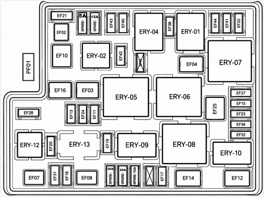
| No. | Specification | Protection Circuit |
|---|---|---|
| PF01 | 125A | Generator |
| EF02 | 30A | Starting power supply |
| EF03 | 40A | High speed fan |
| EF04 | 40A | Blower |
| EF07 | 30A | EPB R |
| EF08 | 40A | ABS/ESP |
| EF09 | – | Reserved |
| EF10 | 30A | Low speed fan |
| EF11 | 15A | Power supply of horn relay |
| EF12 | 60A | IEC power supply 2 |
| EF13 | – | Reserved |
| EF14 | 60A | IEC power supply 1 |
| EF15 | 5A | IBS |
| EF16 | 60A | EPS |
| EF17 | 15A | Fuel pump |
| EF18 | 5A | Blower |
| EF19 | 20A | Front wiper |
| EF20 | 5A | EMS ST |
| EF21 | 10A | A/C compressor |
| EF22 | 10A | EMS power supply |
| EF23 | 15A | TCU |
| EF24 | 25A | ABS valve |
| EF25 | 30A | EPB L |
| EF26 | – | Reserved |
| EF27 | 15A | High beam |
| EF28 | – | Reserved |
| EF31 | 10A | Brake switch power supply |
| EF32 | 10A | Left low beam |
| EF36 | 10A | Right low beam |
| EF38 | 5A | Start feedback signal |
| EF40 | 10A | O2 sensor |
| EF41 | 10A | Fuel injector |
| EF42 | 20A | Electronic vacuum pump |
| EF43 | 10A | EMS 15A |
| EF44 | 15A | Ignition coil |
| ERY01 | – | Main relay |
| ERY02 | – | Electronic vacuum pump relay |
| ERY04 | – | Starting relay |
| ERY05 | – | Low speed fan relay |
| ERY06 | – | High speed fan relay |
| ERY07 | – | Blower relay |
| ERY08 | – | Front wiper relay 1 |
| ERY09 | – | Front wiper relay 2 |
| ERY10 | – | Low beam relay |
| ERY12 | – | Fuel pump relay |
| ERY13 | – | Drive chain R2 relay |
Related Posts: