
Dacia Logan (2013 – 2020) Fuse Box Diagrams & Location
The Dacia Logan (2013–2020) uses fuse boxes to protect important electrical circuits and components. Knowing the correct fuse locations and assignments makes troubleshooting electrical problems easier. This guide covers fuse box locations, diagrams, fuse ratings, and protected components for the Dacia Logan.
Fuse Box Location
Passenger Compartment Fuse Box
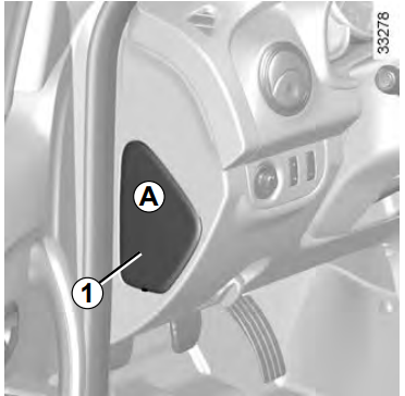
If any electrical component does not work, check the condition of the fuses. Unclip flap A using notch 1 to help you.
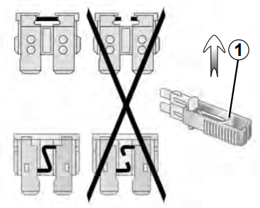
Clip 1
Remove the fuse using tweezers 1, located at the back of flap A. To remove the fuse from the tweezers, slide the fuse to the side. It is not advisable to use the free fuse locations.
Engine Compartment Fuse Box
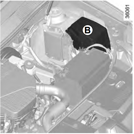
Some functions are protected by fuses located in the engine compartment (unit B). However, because of their reduced accessibility, we advise you to have your fuses replaced by an approved Dealer.
Fuse Box Diagrams
Passenger Compartment Fuse Box
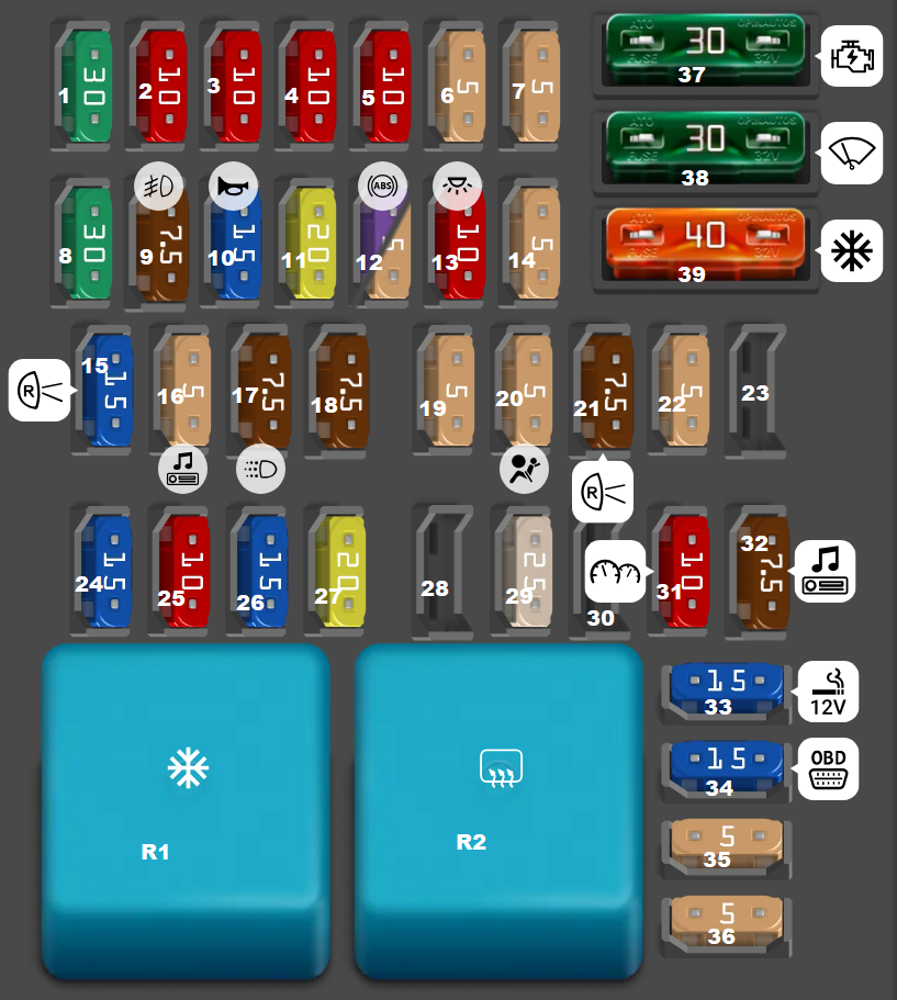
| Type | No. | Description |
|---|---|---|
| Fuse MINI 30A | 1 | Electric glass front lifts |
| Fuse MINI 10A | 2 | High beam left headlight |
| Fuse MINI 10A | 3 | High beam right headlight |
| Fuse MINI 10A | 4 | Low beam left headlight |
| Fuse MINI 10A | 5 | High beam right headlight |
| Fuse MINI 5A | 6 | Rear dimensions, number illumination, illumination |
| Fuse MINI 5A | 7 | Front dimensions |
| Fuse MINI 30A | 8 | Electric glass rear lifts |
| Fuse MINI 7.5A | 9 | Rear fog lamp |
| Fuse MINI 15A | 10 | Horn |
| Fuse MINI 20A | 11 | Central locking |
| Fuse MINI 3A | 12 | ABS/ESP |
| Fuse MINI 5A | 12 | ABS/ESP |
| Fuse MINI 10A | 13 | Interior lighting, air conditioning |
| Fuse MINI 5A | 14 | Steering angle sensor |
| Fuse MINI 15A | 15 | Glass washer, parking radar, reversing light |
| Fuse MINI 5A | 16 | Audio system, heated glass, speed limiter |
| Fuse MINI 7.5A | 17 | DRL |
| Fuse MINI 7.5A | 18 | Brake light |
| Fuse MINI 5A | 19 | Control system |
| Fuse MINI 5A | 20 | Airbags |
| Fuse MINI 7.5A | 21 | Reversing lamp, AMT control unit |
| Fuse MINI 5A | 22 | Electric power steering pump |
| Fuse MINI 15A | 24 | Direction indicator |
| Fuse MINI 10A | 25 | Anti-theft system |
| Fuse MINI 15A | 26 | Electrical control unit |
| Fuse MINI 20A | 27 | Steering column switches (low beam input) |
| Fuse MINI 25A | 29 | Steering column switches (high beam input) |
| Fuse MINI 10A | 31 | Instrument cluster |
| Fuse MINI 7.5A | 32 | Audio system |
| Fuse MINI 15A | 33 | Cigarette lighter |
| Fuse MINI 15A | 34 | Diagnostic connector |
| Fuse MINI 5A | 35 | Heated exterior mirrors |
| Fuse MINI 5A | 36 | Mirror drive |
| Fuse ATO 30A | 37 | Starter |
| Fuse ATO 30A | 38 | Wiper |
| Fuse ATO 40A | 39 | Air conditioner |
| Relay | R1 | Air conditioner relay |
| Relay | R2 | Rear defogger relay |
Engine Compartment Fuse Box
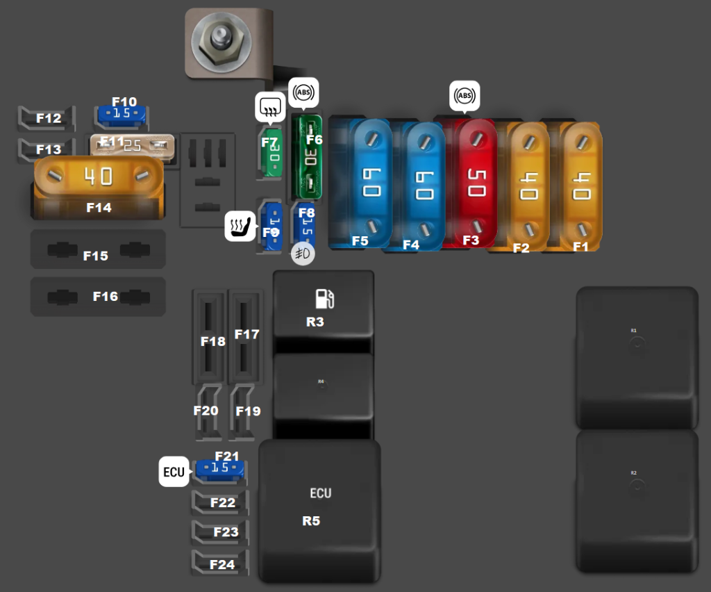
| Type | No. | Description |
|---|---|---|
| Fuse MAXI 40A | F1 | Right windscreen heating element |
| Fuse MAXI 40A | F2 | Left windshield heating element |
| Fuse MAXI 50A | F3 | ABS/ESP |
| Fuse MAXI 60A | F4 | Immobilizer, passenger compartment fuse supply circuit F28-F31 |
| Fuse MAXI 60A | F5 | Power supply for passenger compartment fuses F11, F23-F27, F34 and F39 |
| Fuse ATO 30A | F6 | ABS/ESP |
| Fuse MINI 30A | F7 | Heated rear window and mirrors |
| Fuse MINI 15A | F8 | Front fog lights |
| Fuse MINI 15A | F9 | Heated seats |
| Fuse MINI 15A | F10 | Air conditioner clutch (equipment with air conditioning) / 25A First speed of electric fan (equipment without air conditioning) |
| Fuse ATO 25A | F11 | Fuse for the relay of the engine management system |
| Fuse MAXI 40A | F14 | Electro cooling fan |
| Fuse MINI 15A | F21 | Engine management system |
| Relay | R1 | Relay for left glass heating |
| Relay | R2 | Relay for the right glass heating |
| Relay | R3 | Fuel pump relay |
| Relay | R4 | Relay for the air conditioner compressor or the first speed of the electric fan (depending on the configuration) |
| Relay | R5 | Engine control relay |
Related Posts: