
MINI Countryman R60 (2010 – 2016) Fuse Box Diagrams & Location
This article covers the MINI Countryman R60 (2010–2016) fuse box locations, fuse assignments, and diagrams. Find the correct fuse panel, understand each fuse’s function, and identify the circuits protected by individual fuses for easier troubleshooting and maintenance.
Fuse Box Location
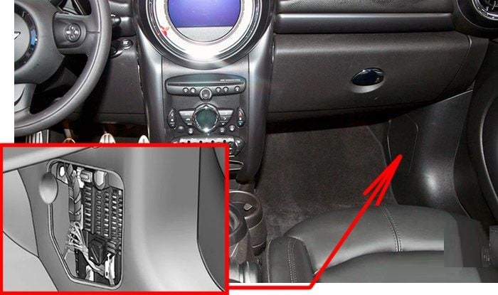
Passenger Compartment Fuse Box
The fuse box is located on the right side of the footwell, in the side trim.
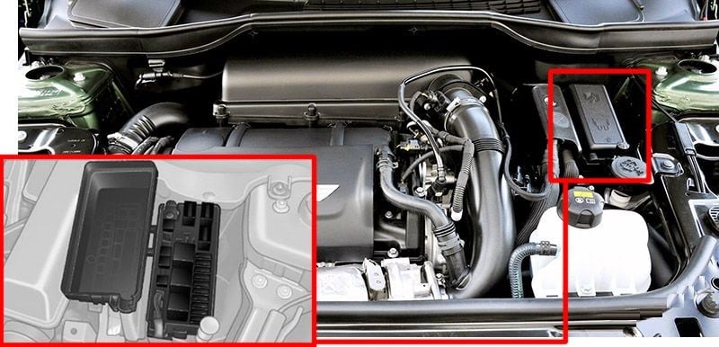
Engine Compartment Fuse Box
Press the snap lock to open.
Fuse Box Diagrams
Passenger Compartment Fuse Box
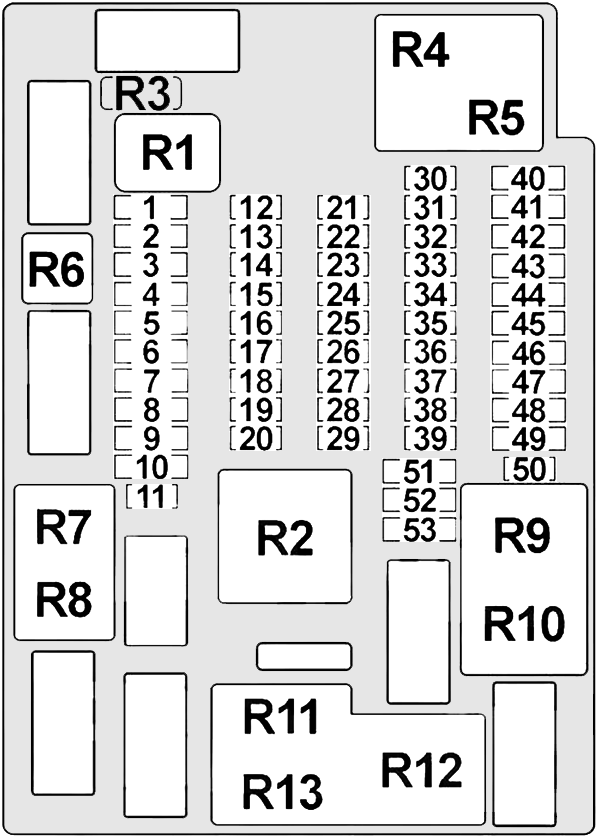
| № | Amps | Protected Component |
|---|---|---|
| 1 | – | – |
| 2 | 30A | Headlight Washer Relay, Headlight Washer Pump Relay |
| 3 | 30A | Trailer Module |
| 4 | 30A | Footwell Module |
| 5 | – | – |
| 6 | 30A | Sunroof |
| 7 | 20A | Trailer Socket |
| 8 | 30A | Footwell Module |
| 9 | 30A | Countryman: Rear Driver’s Side Power Window Motor, Rear Passenger’s Side Power Window Motor |
| 10 | 30A | Countryman: Rear Driver’s Side Power Window Motor, Rear Passenger’s Side Power Window Motor |
| 11 | 15A | Driver’s Door System Lock, Passenger’s Door System Lock, Fuel Filler Flap Central Locking (USA) |
| 12 | 5A | Telephone (Base Plate, USB Hub) or Combox |
| 13 | 10A | Japan: Navigation |
| 14 | 10A | Driver’s Door Switch Block, Driver’s Side Outside Mirror |
| 15 | 15A | Transmission Control |
| 16 | 10A | Front Interior Light, Make-Up Mirror Lights, Roof Operating Unit, Luggage Compartment Light |
| 17 | 10A | Steering Column Switch Center |
| 18 | 5A | Dynamic Stability Control (DSC) |
| 19 | 5A | Rain/Headlight Sensor, Tyre Pressure Control (RDC), Hydraulec Shift Unit, Selector Lever Position Switch |
| 20 | 10A | Heating/Air Conditioning System, Glove Compartment Light |
| 21 | 10A | Control Access Control Unit |
| 22 | 7.5A | Countryman: Outside Mirror Fold-in Paceman: Passenger’s Side Outside Mirror |
| 23 | 10A | MINI Joystick, Central Information Display |
| 24 | 10A | A/C Compressor Clutch Relay |
| 25 | 15A | Windscreen Washer Pump |
| 26 | 5A | Electrochromic Interior Rearview Mirror, Selector Lever Position Switch (USA, Canada, Australia) |
| 27 | 7.5A | Siren with Tilt Alarm Sensor |
| 28 | 15A | Driver’s Door System Lock, Passenger’s Door System Lock, Rear Driver’s Side System Lock (Countryman), Rear Passenger’s Side System Lock (Countryman), Fuel Filler Flap Cantral Locking Drive (EU) |
| 29 | 5A | OBD-II Socket, Additional Instrument |
| 30 | – | – |
| 31 | 5A | N47: Fuel Heater, Electric Auxiliary Heater W16: Electric Auxiliary Heater, Telephone Retrofit Packages Connector |
| 32 | 5A | Park Distance Control (PDC) |
| 33 | 5A | AUC Sensor, DC/DC Converter |
| 34 | 7.5A | Mirror Adjustment Switch, Driver’s Seat Heating Module, Passenger’s Seat Heating Module, Electrochromic Interior Rearview Mirror |
| 35 | 5A | DSC Sensor |
| 36 | 5A | Car Access System |
| 37 | – | – |
| 38 | 5A | Japan: Navigation |
| 39 | – | – |
| 40 | 30A | Rear Window Defogger Relay |
| 41 | 30A | Passenger’s Seat Heating Module |
| 42 | 30A | Driver’s Seat Heating Module |
| 43 | 20A | Trailer Module |
| 44 | 20A | Front Cigar Lighter, Rear Charging Socket |
| 45 | 20A | Radio, Central Information Display (with CCC/CHAMP) |
| 46 | 20A | Fuel Pump Relay |
| 47 | 20A | Horn Relay, Steering Column Switch Center |
| 48 | 30A | Heating/Air Conditioning System (except IHKA), Blower Motor (IHKA), Blower Output Stage (IHKA) |
| 49 | 30A | Amplifier |
| 50 | 15A | Rear Wiper Motor Relay |
| 51 | 40A | Car Access System |
| 52 | 40A | Footwell Module |
| 53 | 40A | Footwell Module |
Engine Compartment Fuse Box
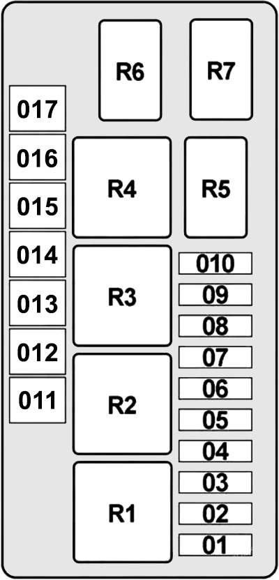
| № | Amps | Protected Component |
|---|---|---|
| 1 | 7.5A | Digital Motor Electronics (DME) Control Unit |
| 2 | 25A | Digital Motor Electronics (DME) Control Unit |
| 3 | 20A | Digital Motor Electronics (DME) Control Unit, Crankcase Ventilation Heater Relay |
| 4 | 20A | Digital Motor Electronics (DME) Control Unit |
| 5 | 7.5A | Diagnostic Module for Fuel Tank Leakage, Electric Fan Relay, Fuel Injectors Relay (Cooper S), Valvetronic Relay (N18, except Cooper S) |
| 6 | 25A | Dynamic Stability Control (DSC) |
| 7 | 7.5A | Crankcase Ventilation Heater Relay (Engine Breather Heater) |
| 8 | 40A | Electric Fan Relay (Electric Fan) |
| 9 | 30A | Wiper Relay №1 & 2 |
| 10 | 15A | Terminal 15 Relief Relay (Electronics Junction Box, Digital Motor Electronics (DME) Control Unit) |
| 11 | 40A | Dynamic Stability Control (DSC) |
| 12 | 50A | Diesel: Fuel Heater |
| 13 | – | – |
| 14 | 50A | Electric Fan Relay №2 (Electric Fan, Digital Motor Electronics (DME) Control Unit) |
| 15 | 50A | Windscreen Heater Relay |
| 16 | – | – |
| 17 | 30A | DC/DC Converter |
| Back Side: | ||
| 1 | – | – |
| 2 | 60A | Diesel: Preheating Control Unit |
| 3 | – | – |
| 4 | 80A | Electromechanical Power Steering |
| 5 | – | – |
Related Posts: