
BAIC X7 2026 Fuse Box Diagrams & Location
The BAIC X7 2026 uses fuse boxes to protect important electrical circuits and components. Knowing the correct fuse locations and assignments makes troubleshooting electrical problems easier. This guide covers fuse box locations, diagrams, fuse ratings, and protected components for the BAIC X7.
Fuse Box Location
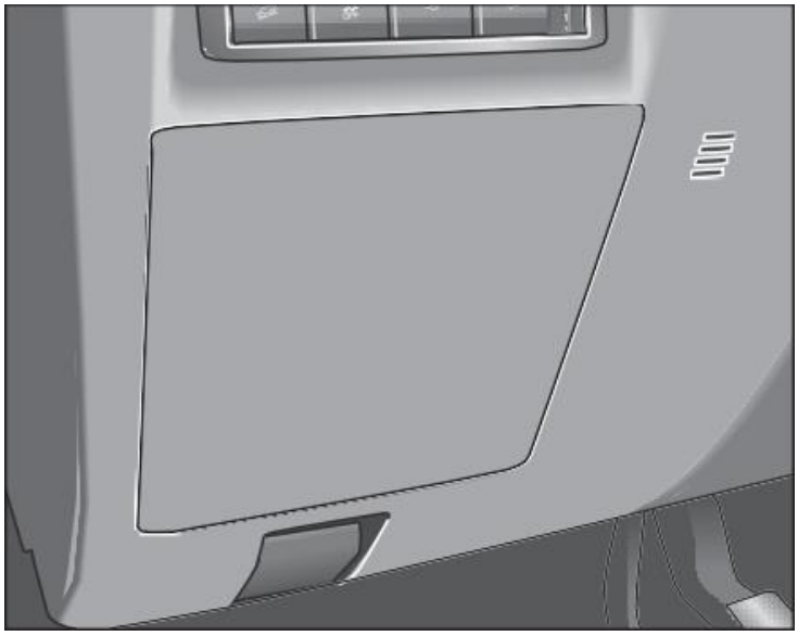
Passenger Compartment Fuse Box
The dashboard fuse box is located on the lower left side of the dashboard and can be seen by removing the fuse box cover on the dashboard.
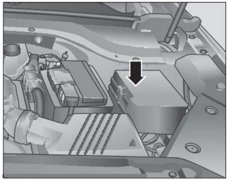
Engine Compartment Fuse Box
The engine compartment fuse box is on the left side of the engine compartment.
Fuse Box Diagrams
Passenger Compartment Fuse Box
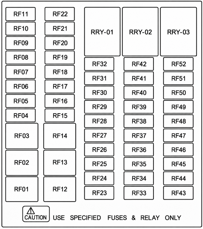
| No. | Specification | Protected Circuit |
|---|---|---|
| F01 | 30A | Driver electric seat A* |
| F02 | 30A | Driver electric seat C* |
| F03 | 20A | Radio |
| F04 | 20A | Radio |
| F05 | 20A | Sunroof |
| F06 | 10A | Dash-cam* |
| F07 | 10A | Air Conditioning Controller |
| F08 | 10A | BDC |
| F09 | 10A | Gateway |
| F10 | 10A | Instrument cluster |
| F11 | 20A | Driver’s electric seat B* |
| F12 | 30A | BDC |
| F13 | 30A | Electric liftgate controller |
| F14 | 30A | BDC |
| F15 | 20A | Left front window lifter |
| F16 | 20A | Right front window lifter |
| F17 | 20A | Left rear window lifter |
| F18 | 20A | Right rear window lifter |
| F19 | 25A | Power amplifier |
| F20 | 25A | Rear seat |
| F21 | 15A | Turning wheel heating |
| F22 | 15A | Rear combination lights |
| F23 | 15A | 12V power supply |
| F24 | 5A | BDC power supply |
| F25 | 10A | Sound power supply |
| F26–28 | – | Reserved |
| F29 | 10A | Seat massage |
| F30 | 10A | BDC |
| F31 | 15A | BDC |
| F32 | 15A | BDC |
| F33 | 5A | Electronic gear shifter IG1 |
| F34 | 5A | Instrument cluster IG1 |
| F35 | 10A | Airbag controller |
| F36 | 5A | Reverse sensor IG1 |
| F37 | 10A | A/C controller IG1 |
| F38 | 5A | Millimeter-wave radar IG1 |
| F39–42 | – | Reserved |
| F43 | 15A | On-board power supply IG2 |
| F44 | 10A | USB |
| F45 | 10A | A/C controller IG2 |
| F46 | 5A | BDC IG2 |
| F47 | 5A | Dashboard switch IG2 |
| F48–49 | – | Reserved |
| F50 | 10A | BDC |
| F51 | 15A | BDC |
| F52 | – | Reserved |
| RRY-01 | – | Reserved |
| RRY-02 | – | Reserved |
| RRY-03 | – | Reserved |
Engine Compartment Fuse Box
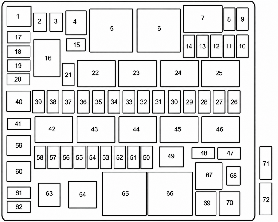
| No. | Specification | Protected Circuit |
|---|---|---|
| 1 | 40A | ESP |
| 2 | – | Reserved |
| 3 | 30A | TCU |
| 4 | 40A | Blower |
| 5 | – | Blower relay |
| 6 | – | Reserved |
| 7 | – | Main relay |
| 8 | 15A | TCU |
| 9 | 10A | EMS |
| 10 | 15A | Ignition coil |
| 11 | 10A | Front/rear oxygen sensor |
| 12 | 10A | OCV |
| 13 | 10A | Fuel injector |
| 14 | 5A | Start feedback signal |
| 15–18 | – | Reserved |
| 19 | 10A | Right front combination lamp |
| 20–21 | – | Reserved |
| 22 | – | IG2 relay |
| 23 | – | Front wiper low-speed relay |
| 24 | – | Front wiper high-speed relay |
| 25 | – | Rear wiper relay |
| 26 | 10A | Rear wiper |
| 27 | 15A | Horn |
| 28 | 10A | Right front fog lamp |
| 29 | 10A | Left front fog lamp |
| 30 | 20A | Electronic vacuum pump |
| 31 | – | Reserved |
| 32 | 10A | Preceding wash |
| 33 | 10A | A/C compressor |
| 34 | 20A | Front wiper low/high |
| 35 | 30A | IG2 |
| 36 | 10A | Left front combination lamp |
| 37 | 10A | Cross lamp |
| 38 | 5A | IBS |
| 39 | 10A | Brake switch power supply |
| 40 | – | Reserved |
| 41 | – | Reserved |
| 42 | – | Rear defroster relay / Accessories relay |
| 43 | – | Reserved |
| 44 | – | IG1 relay |
| 45 | – | Reserved |
| 46 | – | Starter relay |
| 47 | 10A | High Beam |
| 48 | – | Reserved |
| 49 | – | Reserved |
| 50 | – | Reserved |
| 51 | – | Reserved |
| 52 | 30A | IG1 |
| 53 | – | Reserved |
| 54 | 20A | Oil pump |
| 55 | 5A | EPS IG |
| 56 | 5A | EMS IG |
| 57 | 5A | Side mirror heating |
| 58 | 30A | Rear defrosting |
| 59 | – | Reserved |
| 60 | 40A | ESP |
| 61 | 5A | ESP IG |
| 62 | 5A | TCU |
| 63 | 50A | IEC2 |
| 64 | – | Fuel pump relay |
| 65 | – | Reserved |
| 66 | – | Reserved |
| 67 | – | High Beam relay |
| 68 | 30A | Starter |
| 69 | 60A | EPS |
| 70 | 60A | IEC1 |
| 71 | 150A | Alternator |
| 72 | 60A | PWM fan |
Related Posts: