


2025 Genesis G80 Fuses and Fuse Box User Guide
This Guide covers the 2025 Genesis G80 fuses and fuse box, necessary for electrical system maintenance. Examine fuse placements, kinds, and functions for maximum performance.
2024 Genesis G80 Specs, Price, Features, Mileage and Review
Video: 2025 Genesis G80 Fuses
Fuses Guide


A vehicle’s electrical system is protected from electrical overload damage by fuses.
This vehicle has 4 fuse panels, Two are located in the driver’s side panel bolster and engine compartment, the other two are located in the trunk.
If any of your vehicle’s lights, accessories, or controls do not work, check the appropriate circuit fuse. If a fuse has blown, the element inside the fuse will be melted or broken.
If the electrical system does not work, first check the driver’s side fuse panel. Before replacing a blown fuse, turn the engine and all switches off, and then disconnect the negative battery cable. Always replace a blown fuse with one of the same rating.
If the replacement fuse blows, this indicates an electrical problem. Avoid using the system involved and immediately consult an authorized retailer of Genesis Branded products.
WARNING
NEVER replace a fuse with anything but another fuse of the same rating.
- A higher capacity fuse could cause damage and possibly cause a fire.
- Do not install a wire or aluminum foil instead of the proper fuse – even as a temporary repair. It may cause extensive wiring damage and possibly a fire.
NOTICE
Do not use a screwdriver or any other metal object to remove fuses because it may cause a short circuit and damage the system.
Instrument panel Fuse Replacement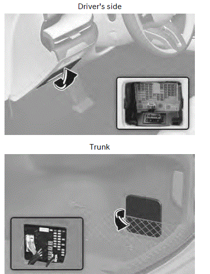
- Turn the vehicle off.
- Turn all other switches off.
- Open the fuse panel cover.
- Refer to the label on the inside of the fuse panel cover to locate the suspected fuse location.
- Pull the suspected fuse straight out. Use the removal tool (1) provided in the engine compartment fuse panel cover.
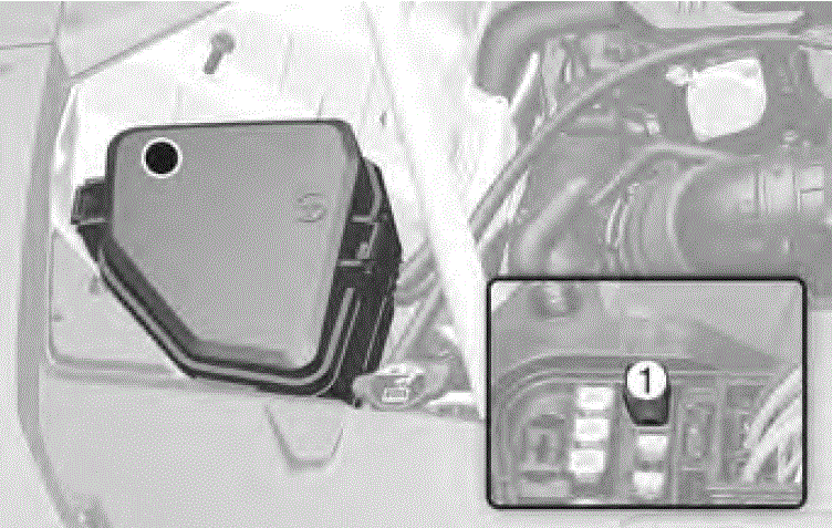
- Check the removed fuse; replace it if it is blown. Spare fuses are provided in the instrument panel fuse panels (or in the engine compartment fuse panel).
- Push in a new fuse of the same rating, and make sure it fits tightly in the clips. If it fits loosely, consult an authorized retailer of Genesis Branded products.
In an emergency, if you do not have a spare fuse, use a fuse of the same rating from a circuit you may not need for operating the vehicle, such as the cigarette lighter fuse.
If the headlights or other electrical components do not work and the fuses are undamaged, check the fuse panel in the engine compartment. If a fuse is blown, it must be replaced with the same rating.
Engine compartment panel fuse replacement
Blade fuse/Cartridge fuse
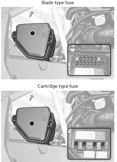
- Turn off the vehicle.
- Turn off all other switches.
- Remove the fuse panel cover by pressing the tap and pulling up.
- Refer to the label on the inside of the fuse panel cover to locate the suspected fuse location.
- Pull the suspected fuse straight out. Use the removal tool provided in the engine compartment fuse panel cover.
- Check the removed fuse and replace it if it is blown. To remove or insert the fuse, use the removal tool in the engine compartment fuse panel.
- Push in a new fuse of the same rating, and make sure it fits tightly in the clips. If it is not tight, contact an authorized retailer of Genesis Branded products.
NOTICE
Always securely install the fuse panel cover. Water may contact the fuse and cause an electrical failure.
Multi fuse/Midi fuse
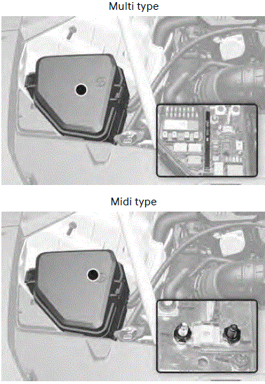 If the multi fuse or midi fuse is blown, consult an authorized retailer of Genesis Branded products.
Fuse/relay panel description
Instrument panel fuse panel
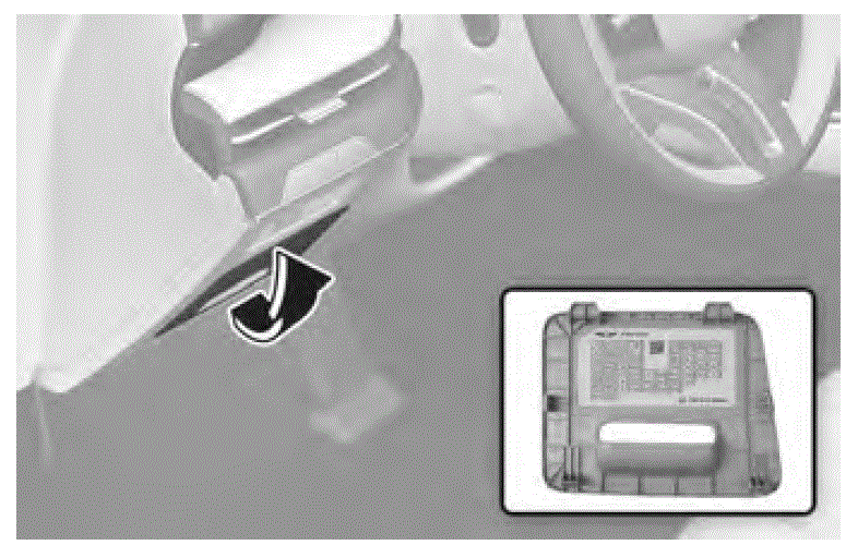
Inside the fuse/relay box cover, you can find the fuse/relay label describing fuse/relay names and ratings.
Information
Not all fuse panel descriptions in this manual may be applicable to your vehicle; the information is accurate at the time of printing. When you inspect the fuse box on your vehicle, refer to the fuse box label.
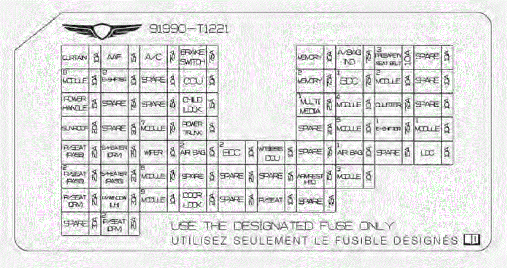
Instrument panel fuse panel
| Fuse Name | Fuse Rating | Circuit Protected |
| CURTAIN | 10 A | BDC |
| ACTIVE AIR FLAP | 15 A | Active Air Flap Module |
| A/C | 7.5 A | E/R Sub Junction Block (LHD : RLY4 / RHD : RLY2), Incar Temperature Sensor, Front A/C Controller, A/C Control Module, Rear A/C Controller |
| BRAKE SWITCH | 7.5 A | Stop Lamp Switch, BDC |
| Fuse Name | Fuse Rating | Circuit Protected |
| MEMORY | 10 A | BDC, Electro Chromic Mirror, Rear A/C Controller, Security Indicator, A/C Control Module, Mood Lamp Module, A/V Navigation Keyboard, Front A/C Controller, Console Mood Lamp LH/RH, Head-Up Display, Crash Pad Mood Lamp LH/RH, Driver/Passenger Door Mood Lamp Unit, Rear Door Mood Lamp Unit LH/RH, Rear Console USB & AUX Jack Assembly [W/O ISG] Front Smart Phone Wireless Charger, ADAS Unit (Parking), Rear Corner Radar LH/RH |
| A/BAG IND | 7.5 A | Over Head Console |
| PRESAFETY SEAT BELT 3 | 10 A | Pre-Active Seat Belt Unit |
| MODULE 8 | 10 A | Data Link Connector, Rain Sensor, Multifunction Switch, ICC Unit, Steering Tilt & Telescopic Unit |
| E-SHIFTER 2 | 10 A | Electronic ATM Shift Lever Dial |
| CCU | 10 A | CCU |
| MEMORY 2 | 7.5 A | Not Used |
| BDC 1 | 7.5 A | BDC |
| MODULE 2 | 10 A | CCU, Stop Lamp Switch |
| POWER HANDLE | 15 A | Steering Tilt & Telescopic Unit |
| CHILD LOCK | 15 A | Child Lock/Unlock Relay |
| MULTI MEDIA 1 | 25 A | [With ISG] Low DC-DC Converter [W/O ISG] CCIC Head Unit |
| MODULE 4 | 10 A | AMP, Driver/Passenger Power Seat Module, Rear Seat Console Remote Control Switch, ICC Unit, Front/Rear Smart Phone Wireless Charger, Armrest Heater Unit, UVC Lamp Unit, Data Link Connector, Low DC-DC Converter, Front/Rear A/C Controller, A/C Control Module, CCIC Head Unit A/V & Navigation Keyboard, Electro Chromic Mirror |
| CLUSTER | 7.5 A | Front Monitor, Head-Up Display |
| SUNROOF | 20 A | Sunroof Control Unit (Master/Slave) |
| MODULE 7 | 7.5 A | 12 V Lithium Auxiliary Battery, Head Lamp LH/RH |
| POWER TRUNK | 10 A | Trunk Open Relay |
| Fuse Name | Fuse Rating | Circuit Protected |
| MODULE 5 | 10 A | Driver Door Module, Multifunction Switch |
| E-SHIFTER 1 | 7.5 A | Electronic ATM Shift Lever Dial |
| MODULE 1 | 10 A | Armrest Lamp, Electronic ATM Shift Level Dial, DCU, CCU, BDC, Front Monitor, AMP, ADAS Unit (Parking), Rear Console USB Charger, Rear Seat Console Remote Control Switch [W/O ISG] CCIC Head Unit, Front Console Keyboard [With ISG] Low DC-DC Converter |
| POWER SEAT (PASS) | 25 A | Passenger Power Seat Module |
| S/HEATER (DRV) | 25 A | Driver Power Seat Module |
| WIPER | 10 A | Multifunction Switch |
| AIR BAG 2 | 10 A | SRS Control Module |
| BDC 2 | 10 A | BDC, Bluetooth Unit #1/#2, UWB Antenna (Trunk), Driver/Passenger Door Outside Handle, Rear Door Outside Handle LH/RH, UWB Antenna (Front LH/RH), UWB Antenna (Rear LH/RH) |
| WIRELESS DCU | 10 A | DCU |
| AIR BAG 1 | 10 A | SRS Control Module, OCCUPANT_DETECTION SYSTEM |
| LDC | 10 A | Front/Rear A/C Controller, Front Console Keyboard, Front/Rear Smart Phone Wireless Charger, Head-up Display, Front Corner Radar LH/RH, Rear Seat Console Remote Control Switch, Rear Console USB & AUX Jack Assembly |
| POWER SEAT (PASS 2) | 25 A | Passenger Power Seat Module |
| S/HEATER (PASS) | 20 A | Passenger Power Seat Module |
| MODULE 6 | 7.5 A | BDC |
| ARMREST HTD | 15 A | Armrest Heater Unit |
| Fuse Name | Fuse Rating | Circuit Protected |
| MODULE 3 | 10 A | Crash Pad Switch, ADAS Unit (Driving/Parking), LKAS Unit, Steering Tilt & Telescopic Unit, Front Console Switch, ECS Unit, RWS Module, ELSD Unit, Rear Corner Radar LH/RH |
| POWER SEAT (DRV) | 25 A | Driver Power Seat Module |
| P/WINDOW LH | 30 A | Rear Power Window Module LH [LHD] Driver Power Window Module [RHD] Passenger Power Window Module |
| MODULE 9 | 10 A | Driver/Passenger Power Seat Switch, Driver/Passenger Power Seat Module, Driver Door Module, Driver/Passenger Power Outside Mirror, PTL Unit [LHD] E/R Sub Junction Block (RLY.2) [RHD] E/R Sub Junction Block (RLY.7) [CCS] Rear Seat LH/RH CCS Unit [Seat Heater] Rear Seat LH/RH Heater Unit [7 Cell] Driver/Passenger Lumbar Support Unit |
| DOOR LOCK | 20 A | Door Lock/Unlock Relay |
| POWER SEAT | 10 A | [7 Cell] Driver/Passenger Lumbar Support Unit |
| POWER SEAT (DRV 2) | 25 A | Driver Power Seat Module |
Engine compartment fuse panel (Engine room junction block)

Inside the fuse/relay box cover, you can find the fuse/relay label describing fuse/relay names and ratings.
Information
Not all fuse panel descriptions in this manual may be applicable to your vehicle; the information is accurate at the time of printing. When you inspect the fuse panel in your vehicle, refer to the fuse panel label.

Engine compartment fuse panel (Engine room junction block)
| Type | Fuse Name | Fuse Rating | Circuit Protected |
| MINE | ALT | 225 A | Alternator |
| MDPS 1 | 125 A | MDPS Unit | |
| MULTI | COOLING FAN | 100 A | Cooling Fan Motor |
| REAR HEATED | 100 A | Rear Heated Relay (RLY.5) | |
| IEB 1 | 60 A | IEB Unit | |
| IEB 2 | 60 A | IEB Unit | |
| IEB 3 | 50 A | IEB Unit | |
| OIL PUMP | 40 A | Electronic Oil Pump | |
| E-CVVT 1 | 40 A | E-CVVT Relay (RLY.1) | |
| AWD | 30 A | AWD ECU | |
| WIPER | 30 A | Wiper Motor |
| Type | Fuse Name | Fuse Rating | Circuit Protected |
| FUSE | HEAD LAMP LH | 40 A | Head Lamp LH |
| START | 30 A | Start Relay (RLY.2) | |
| HEAD LAMP RH | 40 A | Head Lamp RH | |
| B+2 | 40 A | PDC (IPS 11, IPS 12) | |
| MODULE 1 | 10 A | Not Used | |
| FUEL PUMP | 20 A | Fuel Pump Relay (RLY.4) | |
| ECU 1 | 15 A | ECM | |
| TCU 1 | 20 A | TCM | |
| POWER OUTLET | 20 A | Armrest Power Outlet | |
| E-CVVT 2 | 20 A | ECM | |
| E-CVVT 3 | 20 A | ECM | |
| A/C | 15 A | A/C Relay (RLY.3) | |
| HORN | 15 A | PCB Block (Horn Relay) | |
| ACTIVE HOOD 2 | 10 A | Not Used |
Engine compartment fuse panel (PCB block)
| Fuse Name | Fuse Rating | Circuit Protected |
| EWP | 20 A | Electronic Water Pump |
| ECU 2 | 10 A | ECM |
| SENSOR 5 | 10 A | Electronic Oil Pump |
| MODULE 2 | 10 A | Front Corner Radar LH/RH, AWD ECU, Front Radar |
| IEB 4 | 10 A | IEB Unit |
| MDPS 2 | 10 A | MDPS Unit |
| TCU 2 | 15 A | P/N Relay, TCM |
| Fuse Name | Fuse Rating | Circuit Protected |
| ACTIVE HOOD 1 | 10 A | Not Used |
| SENSOR 2 | 10 A | [G4KR] E/R Junction Block (RLY.3), Oil Control Valve (Exhaust), Oil Pump Solenoid Valve, Purge Control Solenoid Valve, RCV Control Solenoid Valve, Canister Close Valve [G6DS] E/R Junction Block (RLY.3), RCV Control Solenoid Valve #1/#2, Purge Control Solenoid Valve, Oil Pump Solenoid Valve, Oxygen Sensor #3/#4, Oil Control Valve #1~#4, Canister Close Valve |
| SENSOR 3 | 10 A | [G4KR] Oxygen Sensor (Up/Down) [G6DS] Oxygen Sensor #1~#2 |
| IGN COIL | 15 A | [G4KR] Ignition Coil #1~#4 [G6DS] Ignition Coil #1~#6 |
| SENSOR 1 | 10 A | [G4KR] Injector #1~#4, E/R Junction Block (RLY.4) [G6DS] Injector #1~#6(MPI), E/R Junction Block (RLY.4) |
| ECU 4 | 20 A | ECM |
| SENSOR 4 | 15 A | Cooling Fan Motor |
| WASHER | 15 A | Washer Relay |
| IG 1 | 30 A | IG1 Relay |
| ECU 3 | 30 A | Engine Control Relay |
| IG 2 | 30 A | IG2 Relay |
| ACC | 30 A | ACC Relay |
Engine compartment fuse panel (Engine room sub junction block)

Inside the fuse panel cover, you can find the panel label describing fuse names and ratings.
Information
Not all fuse panel descriptions in this manual may be applicable to your vehicle; the information is accurate at the time of printing. When you inspect the fuse panel in your vehicle, refer to the fuse panel label.

Engine compartment fuse panel (Engine room sub junction block)
| Fuse Name | Fuse Rating | Circuit Protected |
| BLOWER 1 | 50 A | Blower 1 Relay (RLY.2) |
| BLOWER 2 | 20 A | Blower 2 Relay (RLY.5) |
Trunk fuse panel (Rear sub junction block)

Inside the fuse/relay box cover, you can find the fuse/relay label describing fuse/relay names and ratings.
Information
Not all fuse panel descriptions in this manual may be applicable to your vehicle; the information is accurate at the time of printing. When you inspect the fuse panel in your vehicle, refer to the fuse panel label.

| Fuse Name | Fuse Rating | Circuit Protected |
| B+3 | 50 A | PDC (Fuse – F1/F2/F9/F10/F17/F25/F33/F34/F43/F44/F51/F52/F59) |
| B+1 | 50 A | IPS4, IPS5, IPS6, IPS7 |
| B+5 | 50 A | PDC (Fuse – F36/F38/F49/F53/F56) |
| B+4 | 50 A | PDC (Fuse – F4/F12/F20/F28/F37/F54), IPS13, Long Term
Load Latch Relay |
| LDC 2 | 10 A | Rear Corner Radar LH/RH, ADAS Unit (Parking) |
| P/WINDOW RH | 30 A | Driver/Passenger Power Window Module, Rear Power Window Module RH |
| AMP | 25 A | [W/O ISG] AMP [With ISG] Low DC-DC Converter |
| Fuse Name | Fuse Rating | Circuit Protected |
| POWER DOOR (RR LH) | 15 A | Rear Door Latch LH |
| POWER DOOR (PASS) | 15 A | Passenger Door Latch |
| e-LSD | 20 A | e-LSD Unit |
| PRESAFETY SEAT BELT 1 | 30 A | Pre-Active Seat Belt Unit |
| POWER DOOR (RR RH) | 15 A | Rear Door Latch RH |
| ECS | 15 A | ECS Unit |
| POWER DOOR (DRV) | 15 A | Driver Door Latch |
| PRESAFETY SEAT BELT 2 | 30 A | Pre-Active Seat Belt Unit |
| POWER SEAT (RR) | 20 A | Not Used |
| AMP | 15 A | Not Used |
| SEAT HEATER (RR LH) | 20 A | [CCS] Rear Seat LH CCS Unit [Seat Heater] Rear Seat LH Heater Unit |
| POWER TRUNK | 30 A | PTL Unit (Power Trunk Lid) |
| SEAT HEATER (RR RH) | 20 A | [CCS] Rear Seat RH CCS Unit= [Seat Heater] Rear Seat RH Heater Unit |
Trunk fuse panel (Battery junction block)

Inside the fuse panel cover, you can find the panel label describing fuse names and ratings.
Information
Not all fuse panel descriptions in this manual may be applicable to your vehicle. When you inspect the fuse panel on your vehicle, refer to the fuse panel label.

Trunk fuse panel (Battery junction block)
| Fuse Name | Fuse Rating | Circuit Protected |
| B+9 | 125 A | E/R Junction Block (B+) |
| B+6 | 100 A | Rear Junction Block (Fuse – SB3/F6/F9/F15/F18/F21/F23) |
| B+7 | 100 A | Rear Junction Block (Fuse – SB4/F13/F19/F24/F25/F26) |
| B+8 | 100 A | Rear Junction Block (Fuse – SB1/SB2/F11/F14/F17/F20) |
| AMS | 10 A | Battery Sensor |
| AUX BATT | 50 A | 12 V Lithium Auxiliary Battery |
| RWS | 100 A | RWS Module |
Useful Links:
2024 Genesis G80 Specs, Price, Features, Mileage and Review
2025 Genesis G80 Wipers and Washers User Guide
2025 Genesis G80 Interior and Exterior Light User Guide