
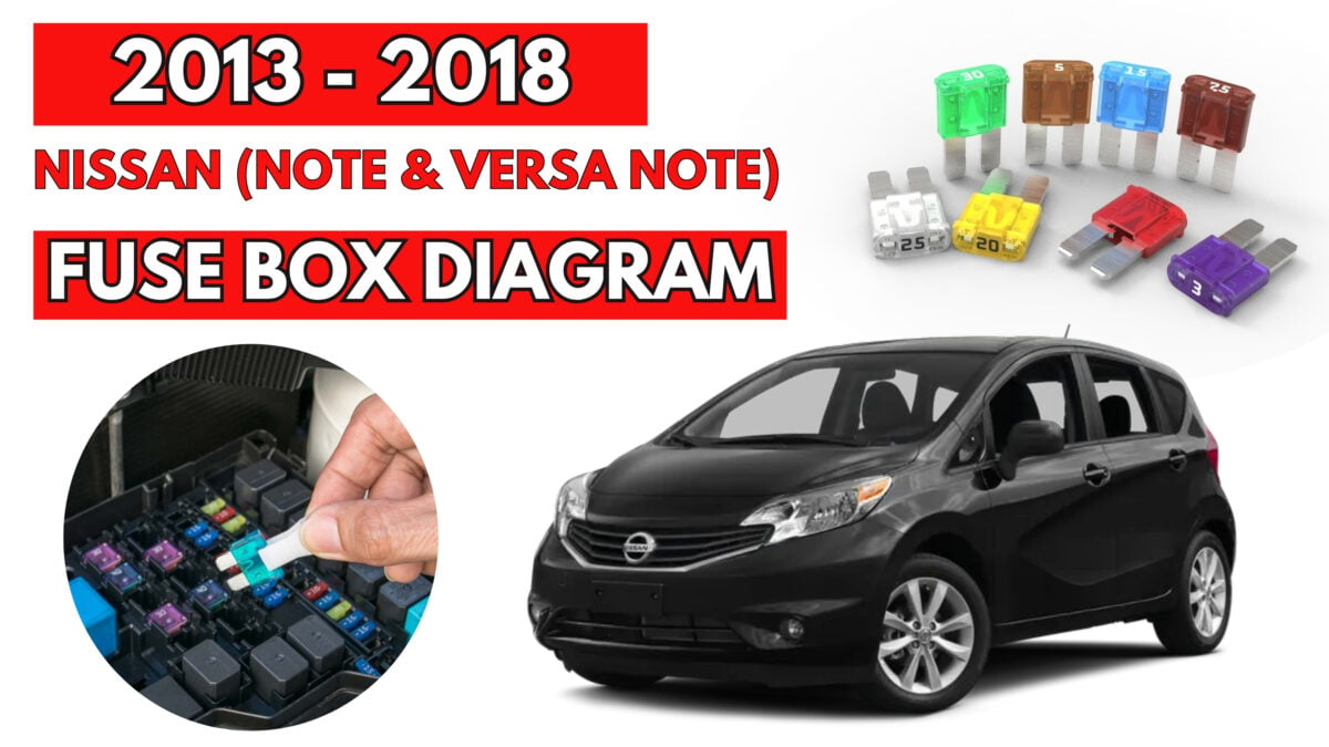

2013 – 2018 Nissan (Note & Versa Note) Fuse Box Diagrams & Location User Guide
The 2013 – 2018 Nissan Note and Versa Note feature several fuse boxes that control the vehicle’s essential electrical systems, from lights to electronics. Knowing the exact locations of these fuse boxes is crucial for quick troubleshooting and routine maintenance. This guide provides detailed fuse box layouts and diagrams for easy reference, helping you manage electrical issues efficiently.
Fuse Box Locations
Passenger Compartment Fuse Box
The fuse box is located on the driver’s side of the instrument panel, behind the cover.

Engine Compartment Fuse Box

Additional Fuse Box

Fusible Link Box
It is located on the battery.

Passenger Compartment Fuse Box Diagrams

| № | Amp | Circuit |
|---|---|---|
| 1 | – | – |
| 2 | – | – |
| 3 | 10 | Back-up Lamp BCM (Body Control Module) Base Audio System Brake Control System Charging System CVT Control System Daytime Light System Display Audio System Engine Control System Front Fog Lamp Headlamp Illumination Intelligent Key System/Engine Start Function Meter Navigation System NVIS Parking Lamps License Plate And Tail Lamps Power Distribution System SRS Air Bag Control System Steering Control System Tire Pressure Monitoring System Turn Signal And Hazard Warning Lamps Warning Chime System |
| 4 | – | – |
| 5 | 10 | BCM (Body Control Module) CVT Shift Lock System Engine Control System Electronically Control Power Steering System Display Audio System Headlamp Aiming System – Manual Power Distribution System Rear Window Defogger Navigation System Steering Control System |
| 6 | 10 | Front Wiper And Washer System Rear Wiper And Washer System BCM (Body Control Module) Power Distribution System |
| 7 | 10 | SRS Air Bag Control System Power Distribution System |
| 8 | 10 | Base Audio System BCM (Body Control Module) Brake Control System CVT Control System Daytime Light System Display Audio System Engine Control System Electronically Controlled Power Steering System Front Fog Lamp Headlamp Illumination Intelligent Key System/Engine Start Function Meter Navigation System NVIS Parking Lamps License Plate And Tail Lamps Power Door Lock System SRS Air Bag Control System Tire Pressure Monitoring System Turn Signal And Hazard Warning Lamps Warning Chime System Vehicle Security System |
| 9 | 20 | – |
| 10 | 10 | BCM (Body Control Module) Intelligent Key System/Engine Start Function NVIS Power Distribution System Starting System |
| 11 | 20 | Rear Window Defogger BCM (Body Control Module) |
| 12 | 10 | Interior Room Lamp Illumination BCM (Body Control Module) Daytime Light System Front Fog Lamp Headlamp Headlamp Aiming System – Manual Intelligent Key System/Engine Start Function NVIS Power Window System Power Distribution System Parking Lamps License Plate And Tail Lamps Power Door Lock System Rear Window Defogger Turn Signal And Hazard Warning Lamps Warning Chime System Vehicle Security System |
| 13 | – | – |
| 14 | – | – |
| 15 | 20 | Power Socket (Cigarette Lighter) Power Distribution System |
| 16 | – | – |
| 17 | 10 | Display Audio System Door Mirror Power Distribution System |
| 18 | 10 | Base Audio System BCM (Body Control Module) Meter Display Audio System Power Distribution System Navigation System |
| 19 | – | – |
| 20 | 15 | Air Conditioner |
| 21 | 10 | Air Conditioner |
| 22 | 15 | Air Conditioner |
| Relay | ||
| R1 | Accessory | |
| R2 | Ignition 2 | |
| R3 | Blower |
Engine Compartment Fuse Box Diagrams
| № | Amp | Circuit |
|---|---|---|
| 34 | 10 | Headlights (High Beam) |
| 35 | 10 | Headlights (High Beam) |
| 37 | 10 | Tail Lamp Relay Parking Lamps License Plate Lamps Headlamp Aiming Motor – Manual Daytime Light System |
| 38 | – | – |
| 39 | 30 | Front Wiper And Washer System |
| 40 | 15 | Headlights (Low Beam) |
| 41 | 15 | Headlights (Low Beam) |
| 42 | 10 | Air Conditioner Relay |
| 48 | 15 | Fuel Pump Relay |
| 49 | 10 | Back-Up Lamp BCM (Body Control Module) CVT Control System Engine Control System Intelligent Key System/Engine Start Function NVIS Power Distribution System Navigation System Starting System |
| 50 | 10 | Brake Control System |
| 51 | 10 | Engine Control System |
| 52 | 15 | Throttle Control Motor Relay |
| 53 | 20 | ECM Relay Engine Control System NVIS |
| 54 | 15 | Engine Control System |
| 55 | 10 | Engine Control System |
Additional Fuse Box Diagram

| № | Amp | Circuit |
|---|---|---|
| 23 | – | – |
| 24 | 10 | Charging System Horn Intelligent Key System Vehicle Security System |
| 25 | 10 | CVT Control System |
| 26 | – | – |
| 27 | – | – |
| 28 | – | – |
| 29 | 15 | Base Audio System |
| 29 | 20 | Except Base Audio: Display Audio System, Navigation System |
| 30 | 10 | BCM (Body Control Module) Brake Control System Engine Control System Intelligent Key System/Engine Start Function NVIS Power Distribution System Stop Lamp Warning Chime System |
| 31 | 15 | Front Fog Lamp |
| F | 40 | M/T: Cooling Fan Low Relay, Cooling Fan High Relay |
| F | 50 | CVT: Cooling Fan Low Relay, Cooling Fan High Relay |
| G | 40 | BCM (Body Control Module) Daytime Light System Front Fog Lamp Front Wiper And Washer System Headlamp Headlight Aiming System – Manual Illumination Interior Room Lamp Intelligent Key System/Engine Start Function NVIS, Parking Lamps License Plate And Tail Lamps Power Window System Power Door Lock System Remote Keyless Entry System Rear Window Defogger Rear Wiper Washer System Turn Signal And Hazard Warning Lamps Vehicle Security System Warning Chime System |
| H | 40 | Starting System Ignition Relay (“3”, “5”, “6”, “7” fuses) BCM (Body Control Module) Intelligent Key System/Engine Start Function NVIS “18” fuse |
| I | 40 | – |
| J | 60 | Electronically Controlled Power Steering System |
| K | – | – |
| L | 30 | Brake Control System |
| M | 30 | Brake Control System |
Fusible Link Box Diagram

| № | Amp | Circuit |
|---|---|---|
| A | 120 | Generator, “D”, “E” fuses |
| B | 60 | Ignition 1 Relay (Front Wiper High Relay, Cooling Fan High Relay, Cooling Fan Low Relay, A/C Relay, “48” fuse), “52”, “53” fuses |
| C | 80 | Accessory 1 Relay (“15”, “17” fuses), Blower Relay (“20”, “21”, “22” fuses), “8”, “10”, “11”, “12” fuses |
| D | 100 | “24”, “25”, “29”, “30”, “31”, “F”, “G”, “H”, “J”, “L”, “M” fuses |
| E | 80 | Headlamp High Relay (“34”, “35” fuses), Headlamp Low Relay (“40”, “41” fuses), “37”, “39”, “42” fuses |