
Vauxhall Mokka X (2016–2019) Fuse Box Diagrams & Location
The Vauxhall Mokka X (2016–2019) uses fuse boxes to protect important electrical circuits and components. Knowing the correct fuse locations and assignments makes troubleshooting electrical problems easier. This guide covers fuse box locations, diagrams, fuse ratings, and protected components for the Vauxhall Mokka X.
Fuse Box Location
Passenger Compartment Fuse Box
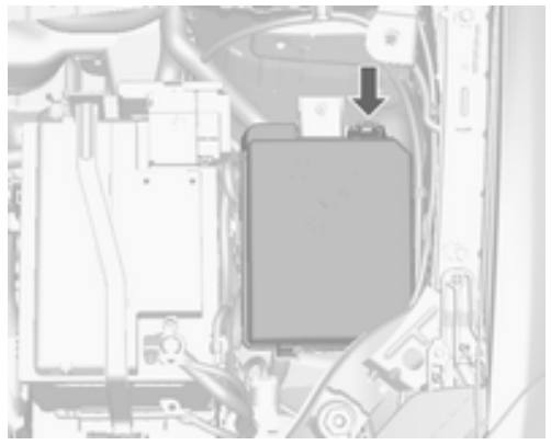
The fuse box is in the engine compartment. Disengage the cover, lift it upwards and remove.
Engine Compartment Fuse Box
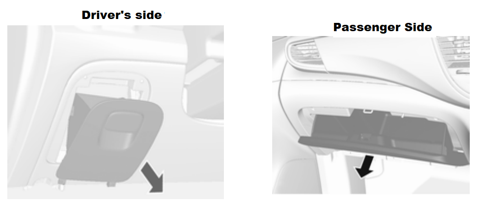
The interior fuse block is located on the underside of the driver’s side instrument panel. To access the fuses, remove the storage. To remove the storage, open and pull it.
Load Compartment Fuse Box
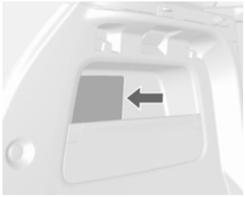
Located on the left side of the rear compartment. To access the fuses, remove the cover.
Fuse Box Diagrams
Passenger Compartment Fuse Box
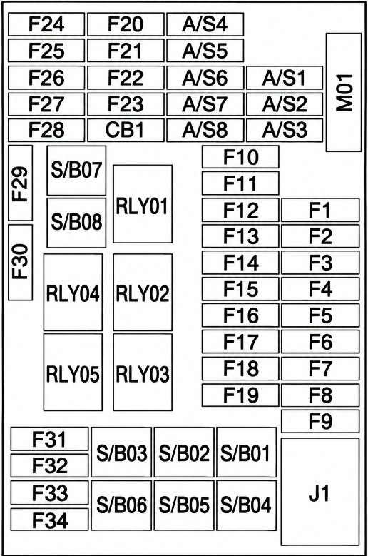
| Fuse No. | Function |
|---|---|
| 1 | Body control module |
| 2 | Body control module |
| 3 | Body control module |
| 4 | Body control module |
| 5 | Body control module |
| 6 | Body control module |
| 7 | Body control module |
| 8 | Body control module |
| 9 | Ignition switch |
| 10 | Safety diagnosis module |
| 11 | Data link connector |
| 12 | Climate control |
| 13 | Tailgate |
| 14 | Central gateway module |
| 15 | Lane departure warning / Interior mirror |
| 16 | Adaptive forward lighting |
| 17 | Column lock |
| 18 | Ultrasonic park assist module |
| 19 | Body control module / Regulated voltage control |
| 20 | Steering wheel |
| 21 | – |
| 22 | Cigarette lighter / DC accessory power outlet (front) |
| 23 | Cigarette lighter / DC accessory power outlet (rear centre console) |
| 24 | Spare |
| 25 | Telematics service module |
| 26 | Heated steering wheel |
| 27 | Instrument panel cluster / Infotainment system / Auxiliary heater switch |
| 28 | Trailer socket |
| 29 | Display / Infotainment system |
| 30 | Transmission control module |
| 31 | Instrument panel cluster |
| 32 | Infotainment system |
| 33 | Trailer socket |
| 34 | Passive entry / Passive start module |
| S/B 01 | Power seat switch |
| S/B 02 | Spare |
| S/B 03 | Power windows front |
| S/B 04 | Power windows rear |
| S/B 05 | Logistic mode |
| S/B 06 | Power seat switch |
| S/B 07 | Spare |
| S/B 08 | Spare |
| M01 | 2017–2019: PTC |
Engine Compartment Fuse Box
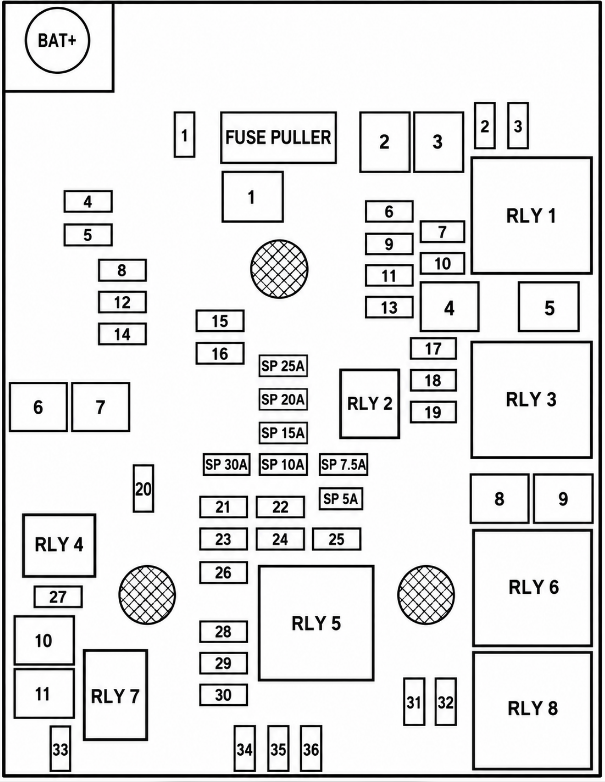
| Type | No. | Circuit |
|---|---|---|
| Mini Fuse | 1 | Sunroof |
| Mini Fuse | 2 | 2016: Exterior mirror switch / Rain sensor; 2017-2019: Exterior mirror switch / Rain sensor / Power window DRV |
| Mini Fuse | 3 | – |
| Mini Fuse | 4 | – |
| Mini Fuse | 5 | Electrical brake control module |
| Mini Fuse | 6 | Intelligent battery sensor |
| Mini Fuse | 7 | Steering column lock |
| Mini Fuse | 8 | Transmission control module |
| Mini Fuse | 9 | – |
| Mini Fuse | 10 | Rear view camera / Interior rear view mirror / Headlight switch / Headlight |
| Mini Fuse | 11 | Rear window wiper |
| Mini Fuse | 12 | Heated rear window |
| Mini Fuse | 13 | Seat, lumbar support |
| Mini Fuse | 14 | Heated exterior mirrors |
| Mini Fuse | 15 | LPG module / Fuel system control module |
| Mini Fuse | 16 | Seat heating |
| Mini Fuse | 17 | Transmission control module R/C / Water pump / Auxiliary heater |
| Mini Fuse | 18 | Engine control module R/C |
| Mini Fuse | 19 | Fuel pump |
| Mini Fuse | 20 | – |
| Mini Fuse | 21 | Cooling fan |
| Mini Fuse | 22 | – |
| Mini Fuse | 23 | Ignition coil / Injectors |
| Mini Fuse | 24 | Washer pump |
| Mini Fuse | 25 | Headlamp actuator |
| Mini Fuse | 26 | Engine control sensors |
| Mini Fuse | 27 | – |
| Mini Fuse | 28 | Ignition |
| Mini Fuse | 29 | Ignition 1/2 |
| Mini Fuse | 30 | Exhaust system |
| Mini Fuse | 31 | Left-hand high beam |
| Mini Fuse | 32 | Right-hand high beam |
| Mini Fuse | 33 | Engine control module |
| Mini Fuse | 34 | Horn |
| Mini Fuse | 35 | Air conditioning system |
| Mini Fuse | 36 | Front fog lamp |
| J-Case Fuse | 1 | Electrical brake control module |
| J-Case Fuse | 2 | Front wiper |
| J-Case Fuse | 3 | Power module |
| J-Case Fuse | 4 | Power terminal of instrument panel fuse box |
| J-Case Fuse | 5 | – |
| J-Case Fuse | 6 | Fuel heater |
| J-Case Fuse | 7 | Starter |
| J-Case Fuse | 8 | Cooling fan |
| J-Case Fuse | 9 | Cooling fan |
| J-Case Fuse | 10 | Engine control module / Glow plug |
| J-Case Fuse | 11 | Starter |
Load Compartment Fuse Box
Fuse Box 2016
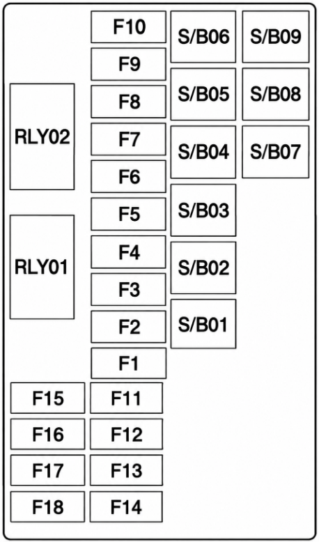
| Fuse Type | No. | Circuit |
|---|---|---|
| Mini Fuse | 1 | – |
| Mini Fuse | 2 | – |
| Mini Fuse | 3 | Amplifier |
| Mini Fuse | 4 | – |
| Mini Fuse | 5 | All-wheel drive |
| Mini Fuse | 6 | Spare |
| Mini Fuse | 7 | – |
| Mini Fuse | 8 | Spare |
| Mini Fuse | 9 | Spare |
| Mini Fuse | 10 | Spare |
| Mini Fuse | 11 | – |
| Mini Fuse | 12 | Spare |
| Mini Fuse | 13 | – |
| Mini Fuse | 14 | – |
| Mini Fuse | 15 | Spare |
| Mini Fuse | 16 | – |
| Mini Fuse | 17 | – |
| Mini Fuse | 18 | – |
| S/B Fuse | 1 | – |
| S/B Fuse | 2 | – |
| S/B Fuse | 3 | – |
| S/B Fuse | 4 | – |
| S/B Fuse | 5 | – |
| S/B Fuse | 6 | – |
| S/B Fuse | 7 | DC/DC 400W transformer |
| S/B Fuse | 8 | DC/DC 400W transformer |
| S/B Fuse | 9 | – |
Fuse Box 2017-2019
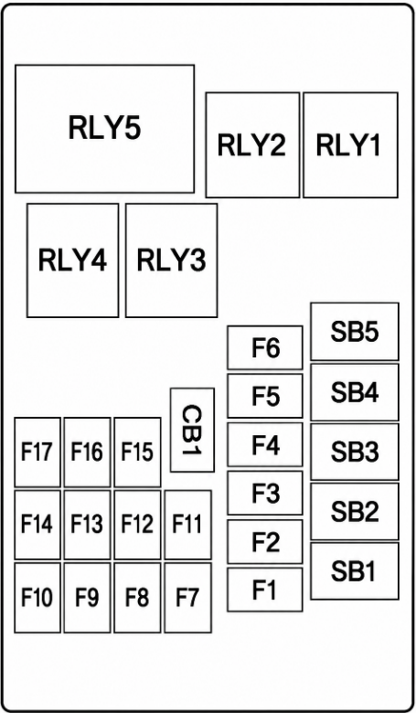
| Fuse No. | Function |
|---|---|
| 1 | Amplifier |
| 2 | All-wheel drive |
| 3 | – |
| 4 | Selective catalytic reduction (2018–2019) |
| 5 | Selective catalytic reduction (2018–2019) |
| 6 | Selective catalytic reduction (2018–2019) |
| 7 | Selective catalytic reduction (2018–2019) |
| 8 | Spare |
| 9 | Spare |
| 10 | Spare |
| 11 | – |
| 12 | Spare |
| 13 | – |
| 14 | – |
| 15 | Spare |
| 16 | – |
| 17 | – |
| 18 | – |
| S/B 1 | DC/DC 400W transformer |
| S/B 2 | DC/DC 400W transformer |
| S/B 3 | – |
| S/B 4 | – |
| S/B 5 | – |
| S/B 6 | – |
| S/B 7 | – |
| S/B 8 | – |
| S/B 9 | – |
Related Posts: